ArticlesArticles Most Popular ArticlesMost Popular Articles Most Helpful ArticlesMost Helpful Articles Submit A QuestionSubmit A Question Login for PRIORITY RESPONSELogin for PRIORITY RESPONSE
RSS Feeds
DrillDown Icon Table of Contents Back
 . . . . . . . . . . . . .
DrillDown Icon Batteries
DrillDown Icon Battery Chargers
DrillDown Icon Motors - Brushless
DrillDown Icon Power Module Set (Electric)
DrillDown Icon Overview
DrillDown Icon Typical Contents
DrillDown Icon Propeller Mounting
DrillDown Icon For VMA-B210X Bird Dog
DrillDown Icon For VMA-C210X Cub & L4
DrillDown Icon For VMA-D210X DO27
DrillDown Icon For VMA-J210X JU52 Trimotor
DrillDown Icon For VMA-N210X Nouvo
DrillDown Icon + READ ME FIRST
DrillDown Icon Think Safety
DrillDown Icon General Information
DrillDown Icon Introduction
DrillDown Icon Contents
DrillDown Icon Installation Instructions
DrillDown Icon Installation Procedure
DrillDown Icon Operating
DrillDown Icon No No's & Must Do's
DrillDown Icon * Support
DrillDown Icon Stay Current - Check Frequently
DrillDown Icon * Additional Information
DrillDown Icon For VMA-P210X PC9 & Texan II
DrillDown Icon For VMA-S210X Aero Subaru
DrillDown Icon For VMA-T210X Twin Otter
DrillDown Icon More Information
DrillDown Icon Tools
DrillDown Icon Power Packs (Electric)
DrillDown Icon Power Supplies
DrillDown Icon Wiring Harness Sets
  Email This ArticlePrint PreviewPrint Current Article/Category and All Sub-Articles/Categories
 
Power Module Set for VMA-N210X Nouvo - Installation Procedure
a) Review the Read Me First documentation and the Assembly & Operations Manual that came with your model.
 
b) In the Operations Manual please turn to Page 7, Stage 11.
 
c) Review (but do not action) all Steps 11A through 11L inclusive. 
 
d) Review Figure 11F showing the wiring between the motor and the electronic speed control ("ESC"). Make sure you plug the wires together as follows:
  • Motor Red Wire to ESC Red Wire
  • Motor Black Wire to ESC WHITE Wire
  • Motor WHITE Wire to ESC Black Wire 

If you do not connect the wires between the motor and the ESC as described above you can damage the motor &/or ESC or the motor may turn backwards.  

e) Review the supplementary information provided below regarding step 11K 

f) After reviewing the steps and the wiring of figure 11F and the supplementary information provided below, proceed carefully with steps 11A through 11L to assemble your power module. 

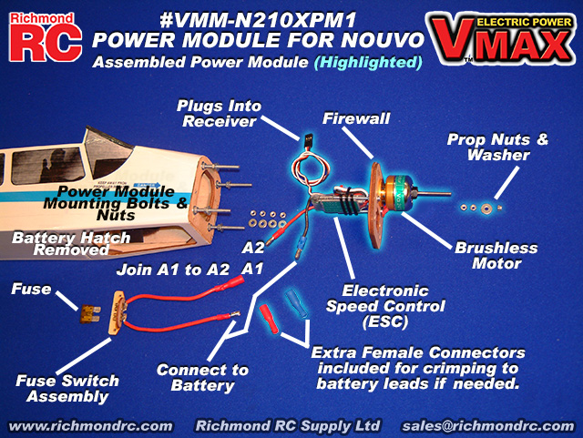
The following depiction illustrates the Fuselage and the assembled Power Module and how it is wired to the Fuse Assembly and Battery Pack: 

VMA-N210X Nouvo 1300 EP 51 in. Electric ARF - Firewall (Power Module) Spacing - Page 7, Figure 11K

This supplementary information applies to manuals with a copyright date of 20070418 (see back cover). Manuals having later copyright dates may already reflect this supplementary information.

Please see Page 7, Figure 11K.

Figure 11K illustrates the spacing between the fixed firewall in the front of the fuselage and the power module firewall to which is attached the motor and speed control.

The picture is correct. However the red type annotated distance shown in Figure 11K of the 20070418 version of the manual is incorrect. The distance should be .39 in. (10 mm).

The actual distance is not particularly critital. What is important is that: 

  • The spacing is equal at all four bolt locations.
  • The cowl can be pushed over the motor and power module firewall and back onto the fuselage with an overlap of 1/8 in. (3 mm)
  • The cowl does not touch the motor itself.


Article ID: 6981