a) Review the Read Me First documentation and the Assembly and Operations Manual that came with your model. Complete Stage 9 from the Assembly and Operations Manual using either a VMAX Power Module set, a VMAX Power Pack or third party motors and speed controllers.
b) After installation of your motors and speed controllers you may install the Power Wiring Harness. Locate the Power Wiring Harness parts bag and remove the harness.
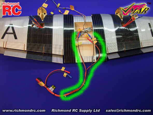
c) Read all labels attached to the Power Wiring Harness. See Figure 3A and the green "path" as a reference to guide you as you proceed with the installation.
|

|
|
3A - Power Wiring Harness Installed - Viewed from Top Side of Wing
|
d) Turn the wing upright so that you can see the large access cavity in the center of the wing where you have installed your ESC's. Support the wing with a sheet of foam rubber or folded up fluffy towel.
e) Position the wing so that the trailing edge (thin) is closer to you and the leading edge (thick) is further away. When oriented in this manner, the wing panel on your left will be the left wing panel in flight and the wing panel on your right will be the right wing panel in flight. This consistent definition of left and right makes it much easier to install the Power Wiring Harness properly.
f) Connect the end of the red Power Wiring Harness marked "+ Power + Positive Left" to the left wing speed control Red (+) power lead.
g) Connect the end of the black Power Wiring Harness marked "- Power - Negative Left" to the left wing speed control Black (-) power lead.
h) This completes the wiring of power to the left wing speed control. Now follow a similar process for the right wing speed control.
f) Connect the end of the red Power Wiring Harness marked "+ Power + Positive Right" to the right wing speed control Red (+) power lead.
g) Connect the end of the black Power Wiring Harness marked "- Power - Negative Right" to the right wing speed control Black (-) power lead.
h) This completes the wiring of power to the right wing and left wing speed controls. Now connect the wiring for the fuselage speed control.
i) Connect the end of the red Power Wiring Harness marked "+ Power + Positive Fuselage" to the fuselage speed control Red (+) lead.
j) Connect the end of the black Power Wiring Harness marked "- Power - Negative Fuselage" to the fuselage speed control Black (-) power lead.
k) Once completed, the left and right speed control and motor assemblies and the fuselage speed control and motor will be connected to the Power Wiring Harness. Separate the quick connect joint (located between the two white zip straps) so that the wing wiring and harness can be removed from the fuselage with the wing.
l) Do NOT plug in your battery pack until you are ready to fly or test your equipment. The battery pack should NOT be plugged in when the model is unattended and should NOT be plugged in when transporting your model in a vehicle.