| VMA-E240X Easy 3D 45-52 ARF - Modify the Fixed Firewall in the Fuselage. | ||||
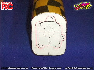
Use Template C. Use scissors to trim to the outer perimeter of the fuselage as shown on Template C. Cut out the inner area of Template C that is bound by the black line. The black line denotes the fixed firewall installed by the factory for electric power systems. Carefully, center, align and attach template C to the forward face of the fixed firewall of the fuselage using adhesive from a glue stick.
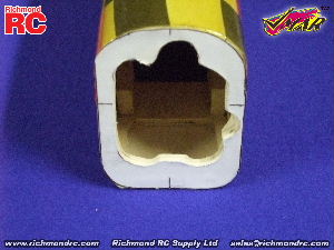
Use a Dremel tool and sanding drum to carve away the fixed firewall to match the red line perimeter of Template C. Work in small steps and test the fit of your power module assembly frequently. Continue carving in small steps with frequent test fits until the fuel tank can be easily inserted into the fuselage from the front and the back face of the power module firewall can be pressed flush against the forward face of the fixed firewall while the power module firewall is centered and aligned.
|

