| 1. VMAR - Hardware & Fittings - General Information |
| 1.1. Axles |
| 1.1.1. Axles - What type of Axle do you use in VMAR ARF products? |
Question: What type of axle do you use in VMAR ARF products? Answer: We have used two main types of axles.
The latter is currently our standard axle and consists of a hardened machine bolt with a socket head and depending on the configuration, related fastening hardware such as retaining safety nut(s), washer(s) and in many cases one wheel collar. This axle has been found to be extremely strong, easy to install and most importantly, it is extremely resistant to vibration loosening of either the axle or the wheel. |
| 1.2. Control Rods |
| 1.2.1. Control Rods - Metal Studs - with 2mm threads |
Question: What type of metal stud threads into the VMAR CNC metal clevis? Will imperial threaded rod work? Answer: The VMAR CNC metal clevis is tapped for 2mm threaded studs. We make precision double ended 2mm studs in various lengths that work well with the VMAR CNC clevis and thread securely into VMAR inner plastic control rod. We have also found that our 2mm studs thread well into other brands of inner plastic rod as well, However we have not tested each and every alternative for compatibility with our 2mm threaded studs. Always test thorougly before and after flying... TUG TUG TUG!
|
| 1.2.2. Control Rods - Plastic with Splines |
Question: What type of plastic control rods do you use? Are they splined or not? Answer: We have used a variety of different plastic control rods since inception in 1999. From mid 2004 onwards we standardized on a new inner/outer plastic rod set. The rod set is of our own design. The inner rod is splined, the outer rod is not. The inner rod accepts our 2mm threaded metal studs and most other brand of studs. Always test for a secure joint when using threaded metal studs.
|
| 1.2.3. Control Rod System - Can it be Changed? |
Question: I have my own favorite control rod system that I would to install on my VMAR ARF. Can the VMAR factory control rod system be changed? Answer: Yes Better Answer: Yes, we use a plastic or metal inner rod sliding in a plastic outer tube. The outer tube will accomodate the inner yellow splined plastic rod from Sullivan. The Sullivan inner rod will in turn accept threaded metal rods or studs which can engage with either plastic or metal clevises. To install your preferred system, simply remove the clevises or EZ connectors from the factory rods and gently pull the factory inner rods out of the fuselage. Then install your preferred system. |
| 1.2.4. Control Rods - Wings - Too Short or Too Long |
Question: When I install my wing servo for the ailerons and/or flaps and/or flaperons the control rod appears to be either too short or too long to connect with the control horns on the control surface. What should I do? Answer: Estimate how much too long or too short the control rods appear to be. If it appears that the discrepancy is about 3/4" then you likely have the servos installed in the wing the wrong way around. Rotate the servo 180 degrees and check again. Most servos have the output shaft closer to one end than the other end and by rotating the servo you in effect change the required length of control rod by about 3/4". |
| 1.3. Clevises |
| 1.3.1. Clevis - Metal (CNC- Pin Diamater - Drill size for Servo Arm |
Question: Should I drill out the holes in my servo arms and/control horns when using the new VMAR CNC produced metal clevis with 2mm screw pin? Answer: VMAR control horns work with the clevis as is. It is not necessary to drill the horns. If you are using a non VMAR horn then we recommend drilling the hole to accomodate a 2mm screw pin. See below. You will find it easier to insert the screw through the hole in the servo arms if you drill them out to 2mm first. It is possible to self tap your way through them using the screws but we don't recommend it. For modelers with access to metric drill bits, use a 2mm drill bit. For modelers with access to imperial drill bits use a 5/64 inch drill bit. Keep in mind that 2mm is what you really want to use... 5/64" is a touch smaller than 2mm. For comparison purposes.
If you are stuck and have neither a 2mm drill bit nor a 5/64" drill bit you can probably find a 1/16" drill bit. This is a bit small but will open up some of the very small holes in the arms of sub-micro servos enough so that with careful pressure you can self tap your way through the arm with the clevis screw. This is not ideal but 1/16" is better than trying to work the clevis screw through some of the very small pin holes in some of the servo arms we have seen on sub-micro servos. For comparison purposes here is some information on 1/16" drill bits.
|
| 1.3.2. Clevises - What type is used in VMAR ARF products? |
Question: What type of clevis do you use in VMAR ARF products? Answer: We have used a number of different clevises.
|
| 1.4. Control Horn Assemblies |
| 1.4.1. Control Horn Installation - How to |
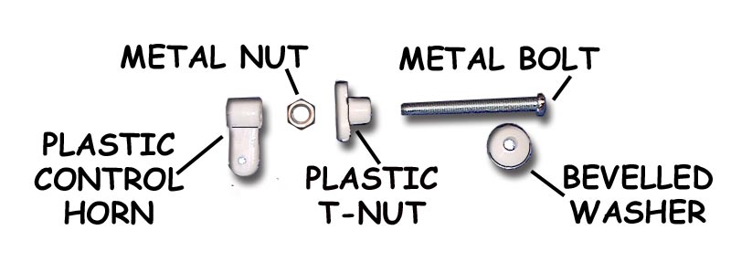
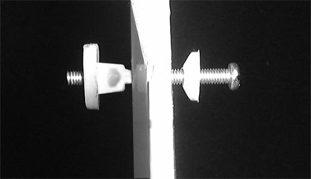
Question: How are VMAR control horns installed? The iillustration below and to the left shows a control horn set before installation. Note 5 parts make up the set. In Light Duty applications the Metal Nut may not be included and only 4 parts will make up the set. The illustration below and to the right shows a control horn set partially installed. Although illustrations in various manuals show the bevelled washer with the bevel pointing away from the surface we find that we get a cleaner strong installation with the bevel pointing inwards. We recommend wicking thin CA such as Pacer ZAP/CA (Pink) into the exposed wood surrounding the hole in the control surface. This helps further strengthen the wood. This is not a requirement but if you are pushing the power limits or planning on extreme aerobatics or speeds, the extra strength could come in handy. Use two applications of thin CA 1 minute apart, BEFORE installing the control horn.
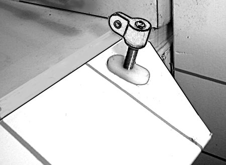
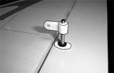
The illustration below shows horn side view of a control horn set fully installed. The illustration to the left is a lighter duty application without the metal nut. The illustration to the right shows a heavier duty application with the metal nut installed. If the metal nuts have been supplied with the horns, we recommend using them.
|
| 1.4.2. Control Horn - Bevelled Washer - Orientation |
Question: The bevelled washer that is a component of the control horn assembly can be oriented in two ways... either with the flat surface facing towards the bolt head or with the flat surface facing away from the bolt head. Which is correct? Answer: Well in most cases it really does not matter. The main thing is to keep the bolt and lock washer hand snug so that nothing loosens up. The assembly and operations manuals generally show the washer with the flat side of the washer towards the control surface and the tapered side of the washer facing towards the bolt head. We actually prefer doing it the other way around so that the flat side of the washer is facing the towards the bolt head and the tapered side of the washer is facing towards the control surface. This helps self center the washer in the control horn hole thereby aligning the entire control horn at right angles to the control surface. This does NOT work well on smaller models with thin control surfaces. For thin control surfaces always have the flat side of the washer facing the control surface. |
| 1.5. EZ Connectors - How to Install. |
| Question: How are the VMAR EZ Connectors Installed? Answer: This is a screw type EZ connector. It works in a similar manner to that of other manufacturers. Remove the set screw (larger) and beneath the set screw there is a small screw that passes like a shaft through the bottom of the EZ connector. Remove the nuts from the external threaded end of the small screw, thread the small screw through the hole in a control horn, steering arm or servo arm and fasten it in place with one or two of the small nuts. Now pass the control rod through the side holes in the EZ connector and lock the rod into place with the set screw. Apply thread locker to retain the set screw and the nut(s). For pictures, modelers may wish to check their instruction manuals. There is a good collection of instruction manuals located on the support section of our web site. This can be accessed through the support button in our On-Line store or directly at http://www.richmondrc.com/support.htm . Some good pictures can be seen in the manual (PDF file) for the VMA-D260D Dornier DO27 on Page 4 (Figure 5.3) and on Page 5 (Figures 6.2 and 6.3) |
| 1.6. Hinges |
| 1.6.1. Hinges - Live - Ultratough and Flexible |
Question: Do VMAR ARFS use so called one piece "Live" hinges or the two piece hinge with a metal pin holding them together? Answer: We have used both in the past but since mid 2003 we have used one piece live hinges. We use a proprietary composite hinge material that has a textured surface and is very flexible, extremely strong and bonds well with CA or Epoxy. Extensive testing and the experience of building 10's of thousands of ARFS using our live hinge material has confirmed that our live hinge allows us to give modelers a nice looking result that is simply the strongest in the industry.
|
| 1.6.2. Hinges - Pinned for Satety |
Question: What do you mean by "pinned hinges"? Answer: When we install the control surfaces using our proprietary composite live hinge material the hinges are glued into place using CA. Then we insert pins through the surfaces and right through both ends of the hinge itself. so that the hinge is trapped into place. The pin is then cut off flush with the surface and pressed further into the substrate. VMAR does this is at least for the hinges are each end of all control surfaces. Question: What's the big deal? Why bother with this? Why are "pinned hinges" better than "un-pinned hinges"? Answer: Most ARF manufacturers throw the control surfaces in the box, give you some rough and ready hinges and leave the job of hinging and installing the control surfaces to you. At VMAR we like to put more ARF in all our ARFS so we install your control surfaces at the factory. By using a super strong hinge, gluing it into place and pinning the hinge as well, we are reducing the chance that a control surface will come off in flight. As the builder and flyer of any model, you are responsible for all aspects of flight safety and integrity of the model no matter how much factory work has been done in advance... but we like to help you with this responsibility with a really good hinge, a really good hinge system and pins! Remember... tug tug tug, test test test before and after each flight. If something is going wrong or loosening up or a sloppy fit is creeping into play, you want to find out on the ground... not in the air! |
| 1.6.3. Hinges - Preinstalled Control Surfaces - Alignment & Gap |
Question: Do VMAR ARF products come with the control surfaces pre-installed by the factory? Can I expect a clean hinging job and the correct hinge gap? Answer: Yes Yes and Yes! We put more ARF in our ARFS than anyone in the business so we install the control surfaces for you. This is a real time saver and frankly, most people have trouble getting the control surfaces aligned in all three axis's and a hinge gap that is a gap not a GAP! We have a factory system for doing this and the system turns out a clean installation with consistently good alignment and just the right amount of hinge gap. |
| 1.6.4. Hinges - Hinge Line Gap - Can it be reset? |
Question: I want to increase the throws of my control surfaces. This requires increasing the hinge line gap. Can I do this? Answer: Yes you can increase the hinge line gap to allow more movement of the control surfaces but you should NOT exceed the maximum recommended "throws" for your particular model. Increasing the hinge line gap &/or exceeding the maximum recommended throws can lead to unpredictable results &/or control surface flutter and may result in loss of control and a crash. If you are sure that you want to do this here is what to do:
|
| 1.7. Small Square Wood Blocks with Slots. What are they for? |
Question: There are some small square wood blocks with slots in one side in my hardware pack. What are they for? Answer: These are included with some of the VMAR ARF's as an extra item to be used if you wish to guide control rods at the servo end of the rod. They can be stacked or glued individually to the fuselage side with the slot "around" the rod to prevent the rod from flexing. With most installations they are no longer needed but if you find that the control rod flexes up or down you can trap the rod in the guide slots to limit the motion. |
| 1.8. Spinners |
| 1.8.1. Spinner - Collets - Plastic Rings on a Tree |
Question: My VMAR ARF model came with a very complete set of Hardware & Accessories. I have one item that I am not sure about. Its a plastic "tree" with 8 rings on it. They look like they are intended to be a spacer or collet. What are they for? Answer: These are collets for adapting VMAR spinners to various crankshaft diameters. Most VMAR ARF's now come with metal spinners that have a brass collett and generally do not require the plastic collets. But there may be some modelers who need to adapt a spinner to their crankshaft so we have included the 8 plastic rings (collets) with some models. In most cases they will not be required. |
| 1.8.2. Spinners - Metal - Used on Most VMAR ARFS |
Question: Does a spinner come with a VMAR ARF? Is the spinner plastic or metal? Answer: With few exceptions (such as small electric and small glow engine ARF's) VMAR ARF's come with a spinner. Most of the lower price point products such as Trainers come with a good quality plastic spinner. Mid and higher end products and even some of the lower priced sport and fun fly products come with a VMAR metal spinner. Yes this is entirely metal. The back plate is either steel or aluminum and the cone is aluminum as is the mounting hardware with the exception of the steel center screw. In the case of several of our Jets (prop), the metal spinner is sized and shaped for a scale look, for example the Mig21 has a pointed narrow spinner and the F4U Phantom has an elongated bullet like spinner.
|
| 1.8.3. Spinners - Plastic - Better Fit & Use of Socket Head Screws |
Question: Has the VMAR plastic spinner been improved since it was first introduced in 1998? Answer: Yes. In 1998-2000 the spinner did not have a good finsh and used Phillips head screws to retain the cone. In about 2000 (depending on size and color), we introduced hex head machine screws and redid all of the spinner molds to ensure a better fit and a cleaner finish. As of 2005, these plastic spinners remain in use in our lower price point products including most VMAR Trainers. |
| 1.9. Tail Wheel Assemblies |
| 1.9.1. Tail Wheel Flange in Rudder - Hole Not Big Enough |
Many of the VMAR Tail Dragger Models use a flange inserted into the bottom of the Rudder. This flange has a pipe like tube on one end. The tube has a plastic liner with a hole through it like a piece of air line tubing. Resolution: Use a small drill bit and an electric drill to drill a larger hole through the |
| 1.10. Wheels |
| 1.10.1. Wheels - Metal Hub - Work Better, Look Better |
Question: I have heard that VMAR has a new main and nose wheel with a metal hub. Do you mean looks like metal or for real metal? Just how many different styles of wheels have been used in VMAR ARF products? Answer: Well, first of all, YES we have a new main and nose wheel with a metal hub and YES it's real metal, not plastic painted to look like metal. More about the metal hub wheel shortly. As to the different styles of wheel that we have had over the years: Beginning in about 96 or 97 we had a wheel that had a plastic hub and a square shouldered tire. We hated it... it was rather ugly, it was round in a sense, had too much run out in all axis, it worked OK on grass fields but was poor on pavement. At the time, the technology available to us was limited and this wheel was about the best that could be produced at our factory without huge increases in cost. Most modelers trashed these wheels and the wheels that came with most brands of ARFS at that time and installed their own favorite wheel. In 2000 we introduced a new wheel with a better plastic hub and better rounded shoulder tires. It looked way way better, was more true to the concept that wheels should be round, had less run out and worked just fine on grass. Pavement was somewhat problematic if the wheel had any run out. Manufacturing cost was higher but manageable without a price increase to the end user. Anecdotal surveys of field use indicated that 80-90% of modelers with our trainers were using these wheels as is. Usage factors were lower in the intermediate, sport and scale categories. In 2003 we began internal development of a new wheel that would have a better truer hub and help to reduce run out even more and work with round shouldered tires. A large number of sample sets were built and tested. In mid 2004 this wheel entered production and is the metal hub wheel that people are asking about. This wheel is significantly better than anything we had in the past, it works well on grass or pavement, is more consistent in production, looks good and lasts pretty much indefinitely. Prices to consumers purchasing VMAR ARF models did not increase with the introduction of the metal hub wheel. As of mid 2005, the metal hub main and nose wheel has been in production about a year. It is used on almost all models (some of the lower price point products were transitioned over last) and the supply chain is now generally flowing these new wheels into the market. Feedback to date indicates that this wheel is seldom discarded by the modeler. We expect and accept that scale modelers will continue to utilize high end after market replacements for stock wheels.
|
| 1.11. Why we use VMAR brand hardware in our ARF products. |
Question: Why do you use VMAR brand hardware in VMAR ARF products? Answer: Well, there a bunch of reasons. We are pretty flexible and have used alternatives with mixed results. Around 2000 we used an American source for plastic clevises. The quality was acceptable but we found that the metric sizing was not quite what we expected in the way of a match to our metric sized rods. Secondly we took a lot of flak from people who wanted a metal clevis and from everywhere outside the Americas market that wanted European or Japanese hardware. Lastly, there was confusion on the part of buyers who thought all of the hardware came from one Brand Name supplier when in fact it did not. We clearly stated this in our ads and on the box art but unfortunately some folks were confused anyway and complained loudly when they did not get the hardware that they thought they would be getting. So... we made a decision to make our own hardware, all of it! This did the following for us:
|