| 1. Control Horn Assemblies |
| 1.1. Control Horn Installation - How to |
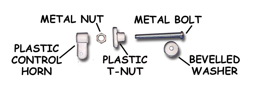
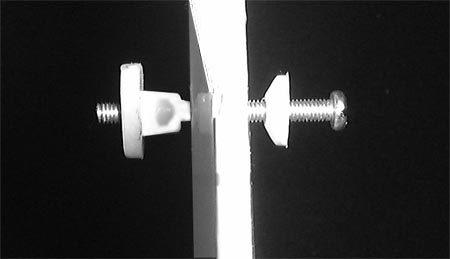
Question: How are VMAR control horns installed? The iillustration below and to the left shows a control horn set before installation. Note 5 parts make up the set. In Light Duty applications the Metal Nut may not be included and only 4 parts will make up the set. The illustration below and to the right shows a control horn set partially installed. Although illustrations in various manuals show the bevelled washer with the bevel pointing away from the surface we find that we get a cleaner strong installation with the bevel pointing inwards. We recommend wicking thin CA such as Pacer ZAP/CA (Pink) into the exposed wood surrounding the hole in the control surface. This helps further strengthen the wood. This is not a requirement but if you are pushing the power limits or planning on extreme aerobatics or speeds, the extra strength could come in handy. Use two applications of thin CA 1 minute apart, BEFORE installing the control horn.
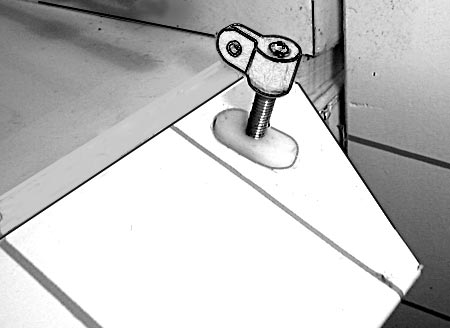
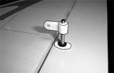
The illustration below shows horn side view of a control horn set fully installed. The illustration to the left is a lighter duty application without the metal nut. The illustration to the right shows a heavier duty application with the metal nut installed. If the metal nuts have been supplied with the horns, we recommend using them.
|
| 1.2. Control Horn - Bevelled Washer - Orientation |
Question: The bevelled washer that is a component of the control horn assembly can be oriented in two ways... either with the flat surface facing towards the bolt head or with the flat surface facing away from the bolt head. Which is correct? Answer: Well in most cases it really does not matter. The main thing is to keep the bolt and lock washer hand snug so that nothing loosens up. The assembly and operations manuals generally show the washer with the flat side of the washer towards the control surface and the tapered side of the washer facing towards the bolt head. We actually prefer doing it the other way around so that the flat side of the washer is facing the towards the bolt head and the tapered side of the washer is facing towards the control surface. This helps self center the washer in the control horn hole thereby aligning the entire control horn at right angles to the control surface. This does NOT work well on smaller models with thin control surfaces. For thin control surfaces always have the flat side of the washer facing the control surface. |