| 1. VMA-F690X F18 Hornet 60-91 Jet (Prop) ARF - Supplement to the Manual |
| COPYRIGHT |
Copyright Richmond RC Supply Ltd. All rights reserved.
|
| 1.1. VMA-F690X F18 Hornet 60-90 ARF - Control Horns |
|
| Control Horn Installation - How to |
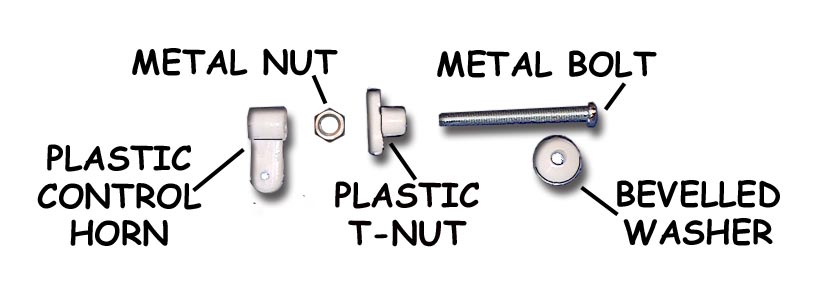
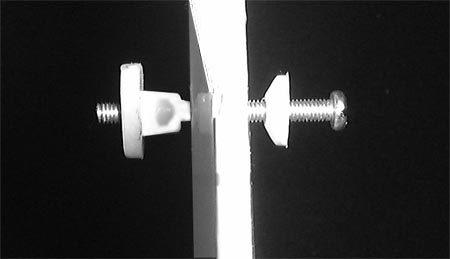
Question: How are VMAR control horns installed? The iillustration below and to the left shows a control horn set before installation. Note 5 parts make up the set. In Light Duty applications the Metal Nut may not be included and only 4 parts will make up the set. The illustration below and to the right shows a control horn set partially installed. Although illustrations in various manuals show the bevelled washer with the bevel pointing away from the surface we find that we get a cleaner strong installation with the bevel pointing inwards. We recommend wicking thin CA such as Pacer ZAP/CA (Pink) into the exposed wood surrounding the hole in the control surface. This helps further strengthen the wood. This is not a requirement but if you are pushing the power limits or planning on extreme aerobatics or speeds, the extra strength could come in handy. Use two applications of thin CA 1 minute apart, BEFORE installing the control horn.
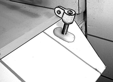
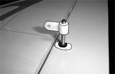
The illustration below shows horn side view of a control horn set fully installed. The illustration to the left is a lighter duty application without the metal nut. The illustration to the right shows a heavier duty application with the metal nut installed. If the metal nuts have been supplied with the horns, we recommend using them.
|
| 1.2. VMA-F690X F18 Hornet 60-90 ARF - Horizontal Stabilizer Fit - Page 6, Figure 6D |
This supplementary information applies to manuals with a copyright date of 20060822 (see back cover). Manuals having later copyright dates may already reflect this supplementary information. Please see Page 6, Figure 6D. Figure 6D shows the fitting of the horizontal stabilizers into the horizontal stabilizer slots in the side aft section of the fuselage. The horizontal stabilizers fit into the slots in the fuselage and are to be seated securely into their respective fuselage slots in the same manner for both the left and right horizontal stabilizers. The distances shown in Figure 6D of the 20060822 version of the manual are incorrect. The "leading edge" distance (bottommost in the picture) should be approximately 16.14 in. (410 mm) and the "hinge line" distance (uppermost in the picture) should be approximately 13.31 in. (338 mm). These distances may vary slightly in production. The important point to note here is that the two horizontal stabilizers should be seated securely into their respective fuselage slots in the same manner for both the left and and right horizontal stabilizers. The actual distances are not as critical as the requirements that:
|
| 1.3. VMA-F690X F18 Hornet 60-90 ARF - Vertical Stabilizer Fit - Page 5, Figure 5C |
This supplementary information applies to manuals with a copyright date of 20060822 (see back cover). Manuals having later copyright dates may already reflect this supplementary information. Please see Page 5, Figure 5C. Step 5.1 and Figure 5C describe and show the dry test fitting of the vertical stabilizers into the vertical stabilizer slots in the top aft section of the fuselage. The vertical stablizers fit into the slots in the fuselage and are to be seated securely into their respective fuselage slots in the same manner for both the left and right vertical stabilizers. The distances shown in Figure 5C of the 20060822 version of the manual are incorrect. The "leading edge" distance (rightmost in the picture) should be approximately 13.58 in. (345 mm) and the "hinge line" distance (leftmost in the picture) should be approximately 11.02 in. (280 mm). These distances may vary slightly in production. The important point to note here is that the two vertical stabilizers should be seated securely into their respective fuselate slots in the same manner for both the left and and right vertical stabilizers. The actual distances are not as critical as the requirements that:
|