1. VMA-T210X Twin Otter 09-15 ARF - Supplement to the Manual

1.1. VMA-T210X Twin Otter 09-15 ARF - Electric Power - Options
Question: My VMAR VMA-T210X Twin Otter 09-15 ARF uses two motors. What do you recommend for a power system?
 
Answer: We have a couple of options for you to consider:
 
1) Our VMAX Power Module for the Twin Otter is #VMM-T210XPM1. This consists of two of our VMAX Brushless Motors (#VMC-120B15VC) and two of our VMAX Electronic Speed Controls (ESC) (#VMC-120B15VC). Each motor and ESC has been factory mounted to a power pylon ready to mate with the wing.
 
2) Our VMAX Power Pack for the Twin Otter (#VMM-T210XPP1) contains the Power Module plus a LiPO battery pack, parallel wiring harness, receiver throttle Y harness and propellers. .
 
Both of these options have been tested with the Twin Otter and help you get into the air quickly and stay there!
 
 
1.2. VMA-T210X Twin Otter 09-15 ARF - Electric Power - Wiring
Question: My VMAR VMA-T210X Twin Otter 09-15 ARF uses two motors. How should I wire these up so that I can control them from the single throttle channel on my receiver?
 
Answer: The simplest solution is to use our VMAX Power Pack which comes with brushless motors, electronic speed controls (ESC), battery pack, propellors etc and includes a custom made Wiring Harness Set for the Twin Otter power and control system. The Power Pack for the Twin Otter is #VMM-T210XPP1.
 
If you have your own motors, servos, speed controls etc that you intend on using in the VMAR Twin Otter the manufacturer of these electric components is your best bet for advice on operating in a Twin Power configuration. The Wiring Harness Set for the Twin Otter (#VMA-T210XWHS) is available as an aftermarket accessory and in most installations will make it much easier to work with the VMAX Power Module, third party motors, speed controls and servos.
 
If you have purchased the VMAX Power Pack for the Twin Otter (#VMM-T210XPP1) please follow the installation instructions that come with the Power Pack. The VMAX Power Pack will save you hours and hours of time and greatly reduce the chances of making an expensive mistake.
 
If you are using third party power components, follow their instructions. In the absence of specific information from the manufacturer here are some general tips that may assist you. Remember, without specific information from the supplier of your Motors and ESC, you run the risk of doing something wrong and such booboos are usually expensive. Use our tips with this in mind. We can't verify that these tips will work with third party equipment and strongly encourage you to obtain information from the manufacturer of your Motors and ESC.
 
a) Use two idential Brushless Motors and two identical Electronic Speed Controls (ESC). Each motor should have its own speed control. (see footnote below)
 
b) Connect each ESC to a Brushless Motor using the color coded wire as a guide. Test and ensure that the motor turns in the direction expected and that thrust is aft of the motor.
 
c) Make a power Y-connector to feed power from your LiPo battery to the power input leads on both of your ESC's. 
 
d) Use the power Y-connector to connect the power input to the ESC's to a common (1) LiPO battery source.
 
e) Make a throttle Y-connector. This is necessary for DUAL ESC operation which assumes that you are using two motors and two ESC's.
 
For DUAL ESC operation use ONLY the NEGATIVE (-) Power (usually black or brown) & SIGNAL lines
(see table below) between the receiver throttle channel and the ESC's.
 
Do NOT use the POSITIVE (+) Power (usually Red) wires.  
The following table serves as a guide to common radio systems and their wiring schema and color usage. Use this table with caution. If in doubt, please defer to information provided by your radio supplier.  
 
RADIO BRAND NEGATIVE (-) SIGNAL
VRS & Futaba Black White
Airtronics Z Black Blue
JR Brown Orange
HiTec Black Yellow
f) Plug the ESC throttle control wires into the ends of the throttle Y-connector
 
g) Plug the remaining single end of the throttle Y connector into your receiver throttle channel.  
 
h) Use the airborne battery pack from your radio system to power your receiver. Do NOT attempt to use power from either BEC to power your receiver. You may wish to consider using a stand alone BEC such as that from Western Robotics to power your radio system but do NOT use the BEC's that are a part of many ESC's. They will not work in a twin power configuration.
 
i) Select suitable propellers for your motors and your speed controllers. The two props should be identical. Prop selection is vital with brushless motors. Overloading the motors and ESC by using the wrong prop can get very very expensive in a big hurry.
 
j) Verify that you can control the RPM of the motors via the receiver and that they produce similar RPM and thrust throughout the throttle range.  
 
Footnote: There are some dual ESC's that enable you to control two Brushless motors from one ESC. These eliminates the need for a second ESC and may make the installation of third party components simpler. If you are using a dual ESC, ensure that you follow the manufacturers instructions regarding wiring and operations.


1.3. VMA-T210X Twin Otter 09-15 ARF - Wing - One Piece or Two?

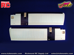
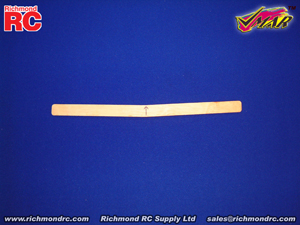
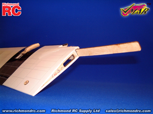
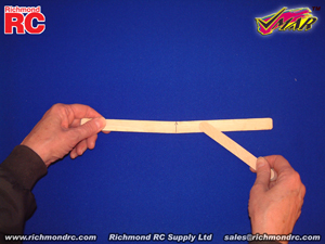
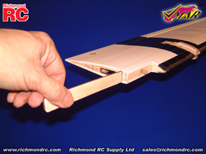
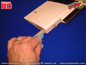
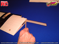
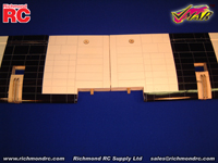
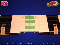
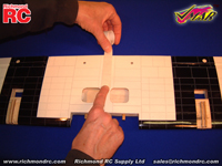
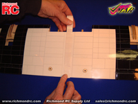
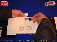
Question: My VMAR VMA-T210X Twin Otter 09-15 ARF refers to a one piece wing. The Twin Otter I received has a two piece wing. What's the story here?

Answer: In some markets, shipping carriers such as UPS charge an additional surcharge for longer boxes. In these markets we have reduced the length of the box by shipping the wing in two pieces in order to save the end consumer from having to pay surcharges on freight.

Additional Information:  If your wing was shipped in two pieces, use the wing joiner and 30 minute epoxy to join the wing halves. A roll of wing joint tape has been supplied to seal the joint after the epoxy has cured. USE ONLY 30 MINUTE EPOXY when joining wing halves.  
 
A subsequent article provides detailed instructions for joining the halves of two piece wings.
 
1.4. VMA-T210X Twin Otter 09-15 ARF - (Stage 0) Wing Assembly - Joining the Wing Halves
 
In some markets we have reduced the length of the shipping box by shipping the wing in two pieces in order to save end consumers from having to pay surcharges on freight. The Assembly and Operations Manual (version 20061031) does not include instructions for joining the wing halves.
 
If your wing was shipped in two pieces, BEFORE BEGINNING Stage 1 of the Assembly and Operations Manual please COMPLETE THE FOLLOWING "Stage 0" INSTRUCTIONS in order to assemble your wing.
 
Parts Supplied:
- Right and left wing panels
- Wing joiner (also called dihedral brace)
- Roll of wing joint tape
Tools & Adhesives needed:
- 30 minute epoxy. Pacer Zepoxy #PAC-30ZPOXY8
recommended. (Do not use 5 Minute Epoxy)
- Epoxy brush or stir sticks
- Disposable mixing dish for the epoxy
- Sandpaper (Coarse 240 grit recommended)
- Low tack masking tape
- Pencil, knife and ruler
- Paper towels

Step 0.1 Locate the wing joiner (also called Dihedral brace). Use a ruler, determine the center of the wing joiner and mark a center line with a pencil as illustrated in 0B.
 
Step 0.2 Locate the wings (See 0A). Trial fit the wing joiner in the channels in the wing panels. You will see two channels in each wing. The channel closest to the leading edge should NOT be used. Insert the wing joiner into the channel that is slightly further aft in the wing. The wing joiner should insert smoothly up to the center line as illustrated in 0C.
 
Now slide the other wing panel onto the wing joiner until the panels meet. If the fit is overly tight, sand the wing joiner slightly and try again. Do not apply excessive force. Sand the joiner until a snug fit is obtained. If the panels slide onto the joiner relatively easily but you end up with a slight gap between the wing panels, trim the ends of the joiner by about 1/8 in. (3 mm) and try again. Work in small steps, testing the results between steps.
 
Mark the joiner to indicate which way is UP as illustrated in 0B.
 

0A - Left & right wing panels

0B - Preparation of wing joiner


Step 0.3
Apply plenty of 30 minute epoxy to all sides of one end (half) of the wing joiner using a stir stick or epoxy brush as illustrated in 0D. Carefully insert the epoxy coated half of the wing joiner into one wing panel as illustrated in 0E. 
 
See 0F and use a cloth or tissue to wipe away any excess epoxy that squeezes out of the joint.
 
Repeat this process several times to ensure the wing joiner and cavity are well coated with 30 minute epoxy.
 
When the wing joiner and cavity are well coated with 30 minute epoxy, insert the joiner to the center line, wipe way any excess epoxy and let dry. (Note: do not use 5 minute epoxy or CA to join the wings).
 

0C - Trial fit the wing joiner

0D - Apply plenty of 30 minute epoxy to the wing joiner

0E - Carefully insert the joiner all the way to the center line

0F - Wipe off the excess epoxy then allow to cure

 
Step 0.4 When the epoxy holding the wing joiner into the first wing panel has cured, trial fit the second wing panel onto the wing joiner (do not glue without trial fitting first) to ensure that the two wing panels fit without an excessive gap.
 
Step 0.5 Now apply plenty of 30 minute epoxy to all sides of the exposed half of the wing joiner (see 0G). Use only 30 minute epoxy to ensure a strong bond and to give yourself plenty of working time. As described in step 0.3, repeatedly apply 30 minute epoxy to the joiner and insert the joiner into the wing joiner cavity to ensure that the wing joiner and the cavity are well coated with 30 minute epoxy.
 
When you have worked plenty of epoxy into the wing joiner cavity, pull the joiner out of the cavity one last time and apply plenty of 30 minute epoxy to the wing root ribs of both panels. Slide the wings together until the wing roots are firmly in contact with each other and there is no gap remaining between the wing panels (see OH). Epoxy should ooze from the joint and be cleaned off with a rag or tissue before it cures.
 
Step 0.6 Use low tack masking tape (see 0I) to align the wing surfaces and to hold the wing panels firmly together until the epoxy cures.
 

0G - Apply plenty of 30 minute epoxy to all surfaces. 

0H - Align the two wing panels and slowly close the gap until the wing roots are firmly in contact with each other.

0I - Use low tack masking tape to hold the wing panels tightly together until the epoxy has completely cured.


Step 0.7  Once the epoxy has cured completely (allow several hours at least), the masking tape can be carefully removed from the wing panels. Peel the tape back on itself... do not pull upright away from the wing.
 
To seal and finish the joint between the wing panels, a roll of wing joint tape has been supplied. Starting on the bottom side of the wing, stick the tape centrally over the joint (see OJ) ensuring that the wing joint tape is pressed down firmly as you work around the wing. Wrap the wing joint tape all the way around the wing in one piece (see OK), starting and finishing on the bottom of the wing (see OL). Trim off any excess tape using a sharp knife.
 

0J - Apply wing joint tape over the joint starting here on the bottom.  

0K - Continue applying the tape over the top of the wing, pressing down firmly as you go.  

0L - Continue back around to the bottom of the wing & overlap the tape where you started. Trim off excess tape.  

NEXT STEPS:

If you are installing a VMAX Power Pack or VMAX Power Module or VMAR Wiring Harness Set, please review the instructions that were supplied with these items now.

Otherwise once you have joined the wing halves, please proceed to Stage 1 of the Assembly and Operations Manual to continue with the assembly of your model.

Pictures are intended to illustrate components and methods of assembly. Production components may vary in detail from that shown.