| 1. Wiring Harness Sets - For VMAX Power Packs | VMAR Wiring Harness Sets for VMAX Power Packs contain all of the wiring and connectors to install and operate the components of multi-motor VMAX Power Packs and any servos included with the power pack. ( Note: Single motor power systems include discrete wiring components and do not use a wiring harness "set" per se.)
VMAR Wiring Harness Sets are factory designed to fit into the applicable VMAR model with its applicable VMAX power system and any included servos. All of the connectors have been factory installed.
VMAR Wiring Harness Sets are:
- Included with VMAX Power Packs for the applicable model.
- Available as a stand alone accessory for use with VMAX Power Modules for the applicable model.
- Provide for fast and reliable installation of VMAX Power Packs and Power Modules into VMAR multi-motor electric models.
- Note: Modelers who are not experienced with multi-motor electric flight systems are strongly encouraged to use the VMAR Wiring Harness Set applicable to their VMAR multi-motor model. Scratch building and installing a reliable wiring harness set for a multi-motor electric model requires approximately 8 hours of work & considerable knowledge and experience.
- May be suitable for use with some third party power systems and servos supplied by end users.
A typical VMAR Wiring Harness Set (WHS) for a multi-motor model contains the following:
- Aileron Wiring Harness (WHA) to connect two aileron servos in the wings to the aileron channel of the receiver in the fuselage.
- (Note: The aileron wiring harness does NOT provide for flaperon operation using a computer radio and two discrete receiver channels. VMAR models utilizing two aileron servos will usually support flaperon functionality in conjunction with the aileron wiring harness if additional aileron extensions are purchased in addition to the aileron wiring harness included with the wiring harness set).
- Throttle Wiring Harness (WHT) to connect multiple Electronic Speed Controls (ESC) to the throttle channel of the receiver in the fuselage.
- Power Wiring Harness (WHP) to provide Positive (+) and Negative (-) power to multiple motors from a single battery (fused in line).
Depending on the model itself the VMAR Wiring Harness Set may also contain:
- Elevator Wiring Harness (WHE) to connect one or more elevator servos located near the tail to the elevator channel of the receiver in the fuselage.
- (Note: In some models the elevator servo is located in a servo tray near the receiver itself and a long control rod connects the servo to the elevator... this arrangement does not require an elevator wiring harness.)
- Rudder & Steering Wiring Harness (WHR) to connect one or more rudder servos located near the tail and a ground steering servo to the rudder channel of the receiver in the fuselage.
- (Note: In some models the rudder servo is located in a servo tray near the receiver itself and a long control rod connects the servo to the rudder... this arrangement does not require an rudder wiring harness. Other models may not offer ground steering via a servo dedicated to controlling a nose or tail wheel and the wiring harness will not provide for such)
- Other wiring harnesses applicable to the particular VMAR model.
|
| 1.1. Wiring Harness Sets - For VMAR Power Packs - Overview | VMAR Wiring Harness Sets for VMAR Power Packs contain all of the wiring and connectors to install and operate the components of multi-motor VMAR Power Packs and any servos included with the power pack. ( Note: Single motor power systems include discrete wiring components and do not use a wiring harness "set" per se.)
VMAR Wiring Harness Sets are factory designed to fit into the applicable VMAR model with its applicable VMAR power system and any included servos. All of the connectors have been factory installed.
VMAR Wiring Harness Sets are:
- Included with VMAR Power Packs for the applicable model.
- Available as a stand alone accessory for use with VMAR Power Modules for the applicable model.
- Provide for fast and reliable installation of VMAR Power Packs and Power Modules into VMAR multi-motor electric models.
- Note: Modelers who are not experienced with multi-motor electric flight systems are strongly encouraged to use the VMAR Wiring Harness Set applicable to their VMAR multi-motor model. Scratch building and installing a reliable wiring harness set for a multi-motor electric model requires approximately 8 hours of work & considerable knowledge and experience.
- May be suitable for use with some third party power systems and servos supplied by end users.
|
| 1.2. Wiring Harness Sets - For VMAR Power Packs - Typical Contents | A typical VMAR Wiring Harness Set (WHS) for a multi-motor model contains the following:
- Aileron Wiring Harness (WHA) to connect two aileron servos in the wings to the aileron channel of the receiver in the fuselage.
- (Note: The aileron wiring harness does NOT provide for flaperon operation using a computer radio and two discrete receiver channels. VMAR models utilizing two aileron servos will usually support computer radio flaperon functionality in conjunction with the aileron wiring harness if additional aileron extensions are purchased in addition to the aileron wiring harness included with the wiring harness set).
- Throttle Wiring Harness (WHT) to connect multiple Electronic Speed Controls (ESC) to the throttle channel of the receiver in the fuselage.
- Power Wiring Harness (WHP) to provide Positive (+) and Negative (-) power to multiple motors from a single battery (fused in line).
Depending on the model itself the VMAR Wiring Harness Set may also contain:
- Elevator Wiring Harness (WHE) to connect one or more elevator servos located near the tail to the elevator channel of the receiver in the fuselage.
- (Note: In some models the elevator servo is located in a servo tray near the receiver itself and a long control rod connects the servo to the elevator... this arrangement does not require an elevator wiring harness.)
- Rudder & Steering Wiring Harness (WHR) to connect one or more rudder servos located near the tail and a ground steering servo to the rudder channel of the receiver in the fuselage.
- (Note: In some models the rudder servo is located in a servo tray near the receiver itself and a long control rod connects the servo to the rudder... this arrangement does not require an rudder wiring harness. Other models may not offer ground steering via a servo dedicated to controlling a nose or tail wheel and the wiring harness will not provide for such)
- Other wiring harnesses applicable to the particular VMAR model.
|
| 1.3. Wiring Harness Set - For VMA-J210X JU52 Trimotor |
| 1.3.1. Wiring Harness Set - #VMA-J210XWHS For VMA-J210X Trimotor - READ ME FIRST | PLEASE READ ME FIRST
BEFORE PROCEEDING TO ASSEMBLE OR OPERATE THIS PRODUCT
|
| LIABILITY DISCLAIMER & COPYRIGHT NOTICE | LIABILITY DISCLAIMER
The authors and/or suppliers and/or disseminaters of this information and/or product expressly disclaim any warranties or representations, either expressed or implied, including but not limited to implied warranties of fitness, accuracy, timeliness or applicability of the information and/or product provided here. In no event will the authors and/or suppliers and/or disseminaters of this information and/or product have any obligation arising from contract or tort, for loss of revenue or profit, or for indirect, special, incidental, consequential or other damages of any sort arising from this information and/or product. In using this information and/or product, the user accepts all responsibility for and all liability associated with such use.
PROCEEDING WITH THE USE OF THIS INFORMATION AND/OR PRODUCT INDICATES AGREEMENT WITH AND ACCEPTANCE OF THE LIABILITY DISCLAIMER.
|
| Please Note the following Caution | CAUTION
A Remote Control (RC) model aircraft is not a toy. It is a flying model that functions much like a full size airplane. If you do not assemble and operate model aircraft properly you can cause injury to yourself and others and damage property. DO NOT FLY a model aircraft unless you are qualified.
You are ultimately responsible for the mechanical, aeronautical and electrical integrity of any model you fly and all of the components that make up the model including but not limited to the airframe itself, control surfaces, hinges, linkages, covering, engine, motor, radio, servos, switches, wiring, battery and parts. Check all components before and after each flight. It is essential that you act with the clear understanding that you are solely responsible for all aspects of the model at all times. DO NOT FLY until it is right.
|
| 1.3.1.1. Wiring Harness Set - For VMA-J210X JU52 Trimotor - General Information | |
|
| COPYRIGHT | Copyright Richmond RC Supply Ltd. All rights reserved.
|
| Tips for Avoiding Common Problems |
We have supplied thousands and thousands and thousands of model aircraft in the past 20 plus years. We're not bragging! We tell you this to give some credibility to our suggested list of tips that follow. In talking to modelers around the world, here is what we have found is the key to...
AVOIDING 90% of PROBLEMS that can arise:
- READ THE CAUTION ABOVE & READ THE LIABILITY DISCLAIMER.You are responsible for all aspects of any model you fly. You're It!
- READ ALL DOCUMENTATION before doing anything else!
- INSPECT CAREFULLY immediately upon arrival!.
- RETAIN ALL PACKAGING until the checkout is complete! If you need to return anything you must have all of the original packaging.
- READ & LOOK! At everything! Do it once & then do it again.
- REMEMBER WHAT "ARF" STANDS FOR. ARF means ALMOST Ready to Fly with an emphasis on ALMOST! Some assembly and modeling skills are required.
- ALLOW ENOUGH TIME to enjoy the assembly process! Rushing into a 6 hour job with 3 hours to spare simply will not work. This is a Hobby... take your time.
- DRY FIT & TEST ASSEMBLE EVERYTHING before you glue anything!
- USE 30 MINUTE EPOXY when joining wings & installing stabilizers and other structural components but only after you have dry fitted and test assembled the components without glue! Once parts are glued together they cannot be unglued and they cannot be returned or replaced without charge.
- PLAN AHEAD! BE CAREFUL! If you get into trouble, DON'T PANIC. Review everything again, talk it over with an experienced modeler and if still in difficulty consult our Support Services.
- TEST TEST!!! TUG TUG TUG!!! EVERYTHING... BEFORE & AFTER EACH FLIGHT! Your model may have been largely pre-constructed and may have pre-installed control rods, hinges, control surfaces and many other essential components. Hinges may have been pinned after they have been installed. However, you must double check every control surface and component before and after each flight. You and only you are responsible for the integrity of all components and the integrity of the model itself. Check everything before and after each flight. Tug on control surfaces, control rods, mounting bolts, T-nuts, mounting plates... tug on everything!
- DO NOT OVER TIGHTEN WING BOLTS or other fasteners. You want bolts and nuts snugly tight and if metal you can use a medium grade thread locker such as Pacer Z42 to help them stay tight. Fasteners must be snug and secure. However a model airplane is not a farm tractor or a garbage compactor. You do not need a pipe wrench or an electric drill to tighten up wing bolts or any other fastener. Leave your plumbing and power tools at home.. hand tools only and go easy on the torque... snug and secure... not stripped or torqued until they squeak or break. Wing bolts can take tremendous torque before breaking... but when you over tighten them or use an electric screw driver on a set of wing bolts, long before the bolts break you can fracture the fuselage, crack the mounting blocks or pull the heads of the bolts through the wing... these problems have a nasty habit of revealing themselves when you least expect the wing to fall off!
- DO NOT OVERPOWER ANY MODEL! Stay within the recommended power range for the model. If you overpower the model you run a high risk of structural failure that will lead to loss of control and a subsequent crash that will destroy the model and may cause injury and/or property damage.
- ASSUME NOTHING! Remember the old yarn about what happens when you ASS-U-ME something. Check everything repeatedly and frequently and DO NOT FLY any model unless you are satisfied that everything is in good working order.
|
| 1.3.1.2. Wiring Harness Set - For VMA-J210X JU52 Trimotor - Introduction | |
Before beginning the Installation Instructions please read the Overview and check off the components provided. Each component is in a labelled parts bag. Please check off the components against the Contents list below. Leave the components in their parts bags for now. Do not remove the components from their parts bags until each is needed during the installation process.
|
| Wiring Harness Sets - For VMAR Power Packs - Overview | VMAR Wiring Harness Sets for VMAR Power Packs contain all of the wiring and connectors to install and operate the components of multi-motor VMAR Power Packs and any servos included with the power pack. ( Note: Single motor power systems include discrete wiring components and do not use a wiring harness "set" per se.)
VMAR Wiring Harness Sets are factory designed to fit into the applicable VMAR model with its applicable VMAR power system and any included servos. All of the connectors have been factory installed.
VMAR Wiring Harness Sets are:
- Included with VMAR Power Packs for the applicable model.
- Available as a stand alone accessory for use with VMAR Power Modules for the applicable model.
- Provide for fast and reliable installation of VMAR Power Packs and Power Modules into VMAR multi-motor electric models.
- Note: Modelers who are not experienced with multi-motor electric flight systems are strongly encouraged to use the VMAR Wiring Harness Set applicable to their VMAR multi-motor model. Scratch building and installing a reliable wiring harness set for a multi-motor electric model requires approximately 8 hours of work & considerable knowledge and experience.
- May be suitable for use with some third party power systems and servos supplied by end users.
|
| 1.3.1.3. Wiring Harness Set - For VMA-J210X JU52 Trimotor - Contents | This VMAR Wiring Harness Set (WHS) contains the following
- Aileron Wiring Harness (WHA) to connect the two aileron servos in the wings to the aileron channel of the receiver in the fuselage. Total Length = approx 32 in. (813 mm). Length from aileron channel connector to Y = approx 7 in. (178 mm)
- (Note: The aileron wiring harness does NOT provide for flaperon operation using a computer radio and two discrete receiver channels. VMAR models utilizing two aileron servos will usually support computer radio flaperon functionality in conjunction with the aileron wiring harness if additional aileron extensions are purchased in addition to the aileron wiring harness included with the wiring harness set).
- Throttle Wiring Harness (WHT) to connect three Electronic Speed Controls (ESC) to the throttle channel of the receiver in the fuselage. Total Length = approx 12.5 in. (318 mm). Length from throttle channel connector to Y = approx 6 in. (152 mm)
- Power Wiring Harness (WHP) to provide Positive (+) and Negative (-) power to three motors from a single battery (fused in line). Total Length = approx 14 in. (355 mm). Length from battery connector to quick disconnect joint = approx 5.0 in. (127 mm)
This VMAR Wiring Harness Set also contains:
- Flap Wiring Harness (FHE) to connect the flap servos located in the wing (inboard locations) to the flap channel of the receiver in the fuselage. Total Length = approx 22.5 in. (571 mm). Length from flap channel connector to junction = approx 7 in. (178 mm)
-
End User Wiring Labels
|
| 1.3.1.4. Wiring Harness Set - For VMA-J210X JU52 Trimotor - Installation Instructions | |
Consult any labels carefully, particularly the larger WARNING labels. The labels are largely self explanatory. Reading the labels will save you a great deal of time and help prevent damage to your equipment.
|
| 1.3.1.4.1. Stage 1 - Install Aileron Wiring Harness (WHA) - For VMA-J210X JU52 Trimotor |
a) Review the Read Me First documentation and the Assembly and Operations Manual that came with your model. Complete Stage 1 and Stage 2 from the Assembly and Operations Manual. Once completed you will have assembled the wing.
b) Review Stage 3 from the Assembly and Operations Manual. Locate the Aileron Wiring Harness parts bag and remove the harness.
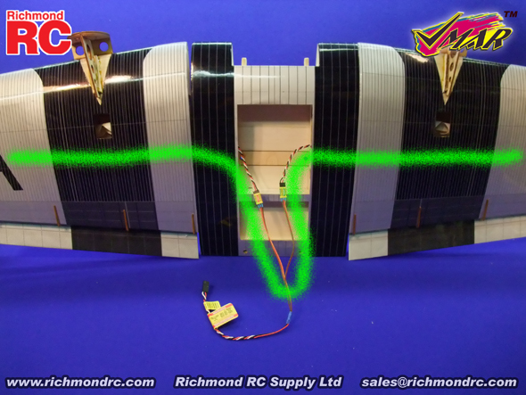
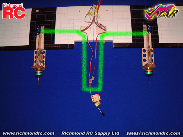
c) Read all labels attached to the Aileron Wiring Harness. Pay particular attention to the larger warning label and note the color conventions used for different manufacturers. This will be important when you plug in your servos and when you plug into your receiver. See Figure 1A and the green "path" as a reference to guide you as you proceed with the installation.
|
|
|
1A - Aileron Wiring Harness Installed - Viewed from Top Side of Wing
|
d) Turn the wing upright so that you can see the large access cavity near the center of the wing. Support the wing with a sheet of foam rubber or folded up fluffy towel.
e) Position the wing so that the trailing edge (thin) is closer to you and the leading edge (thick) is further away. When oriented in this manner, the wing panel on your left will be the left wing panel in flight and the wing panel on your right will be the right wing panel in flight. This consistent definition of left and right makes it much easier to install the aileron servos and aileron wiring harness properly.
f) Thread the end of the wire marked "Aileron Left" through the left side of the large access cavity near the center of the wing and through the internal wiring access tube to the left aileron servo cavity located about 17 in. (432 mm) outboard from the center of the wing. Pull the loose end of the wire out of the tube so that it exits the bottom of the wing through the left aileron servo cavity. Connect the left aileron servo to this wire. Use the supplied "Aileron Left" sticker to wrap the connection securely. Gently pull the wire back from the source and install the left aileron servo into position as shown in Stage 3 of the Assembly & Operations Manual.
g) Repeat this process for the wire marked "Aileron Right", working with the right side of the large access cavity near the center of the wing and the internal wiring access tube that runs to the right aileron servo cavity. Connect the right aileron servo to this wire. Use the supplied "Aileron Right" sticker to wrap the connection securely. Gently pull the wire back from the source and install the right aileron servo into position as shown in Stage 3 of the Assembly & Operations Manual.
h) Once completed, both aileron servos will be installed into the wing and the end of the Aileron Wiring Harness that is labeled "Aileron Channel ==> ==>" will be hanging loose near the center of the wing ready to be plugged into the aileron channel of your receiver.
|
| 1.3.1.4.2. Stage 2 - Install Throttle Wiring Harness (WHT) - For VMA-J210X JU52 Trimotor |
a) Review the Read Me First documentation and the Assembly and Operations Manual that came with your model. Complete Stage 9 from the Assembly and Operations Manual using either a VMAX Power Module set, a VMAX Power Pack or third party motors and speed controllers.
b) After installation of your motors and speed controllers you may install the Throttle Warning Harness. Locate the Throttle Wiring Harness parts bag and remove the harness.
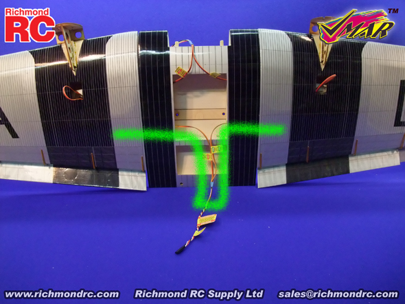
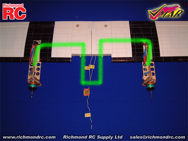
c) Read all labels attached to the Throttle Wiring Harness. Pay particular attention to the larger warning label and note the color conventions used for different manufacturers. This will be important when you plug in your ESC and when you plug into your receiver.See Figure 2A and the green "path" as a reference to guide you as you proceed with the installation.
|
|
|
2A - Throttle Wiring Harness Installed - Viewed from Top Side of Wing
|
d) Turn the wing upright on its back so that you can see your ESC's located in the large access cavity near the center of the wing. Support the wing with a sheet of foam rubber or folded up fluffy towel.
e) Position the wing so that the trailing edge (thin) is closer to you and the leading edge (thick) is further away. When oriented in this manner, the wing panel on your left will be the left wing panel in flight and the wing panel on your right will be the right wing panel in flight. This consistent definition of left and right makes it much easier to install the Throttle Wiring Harness properly.
f) Thread the red, white and black wire lead from the left speed control into the power access cavity located on the top surface of the left wing about 8.5 in. (215 mm) outboard from the center of the wing. Continue feeding the red, white and black wire from the cavity into and though the internal wiring access tube that runs to the large access cavity in the center of the wing. Gently pull the wire so that it protrudes into the large access cavity. Connect this protruding wire to the end of the Throttle Wire Harness marked "Throttle Control Left". Use the supplied "Throttle Left" sticker to wrap the connection securely.
g) Repeat this process for the right wing. Thread the red, white and black wire lead from the right speed control into the power access cavity located on the top surface of the right wing about 8.5 in. (215 mm) outboard from the center of the wing. Continue feeding the red, white and black wire from the cavity into and through the internal wiring access tube that runs to the large access cavity in the center of the wing. Gently pull the wire so that it protrudes into the large access cavity. Connect this protruding wire to the end of the Throttle Wire Harness marked "Throttle Control Right". Use the supplied "Throttle Right" sticker to wrap the connection securely.
h) Once completed, both electronic speed controls for the wing motors will be connected to the Throttle Wiring Harness and the end of the Throttle Wiring Harness that is labeled "Throttle Channel ==> ==>" will be hanging loose near the center of the wing ready to be plugged into the throttle channel of your receiver.
i) Connect the wire marked "Throttle Control Fuselage" to the ESC lead for the fuselage motor when mating the wing to the fuselage. You will unplug this connection when removing the wing from the fuselage.
|
| 1.3.1.4.3. Stage 3 - Install Power Wiring Harness (WHP) - For VMA-J210X JU52 Trimotor |
a) Review the Read Me First documentation and the Assembly and Operations Manual that came with your model. Complete Stage 9 from the Assembly and Operations Manual using either a VMAX Power Module set, a VMAX Power Pack or third party motors and speed controllers.
b) After installation of your motors and speed controllers you may install the Power Wiring Harness. Locate the Power Wiring Harness parts bag and remove the harness.
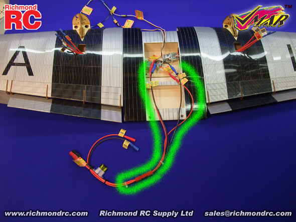
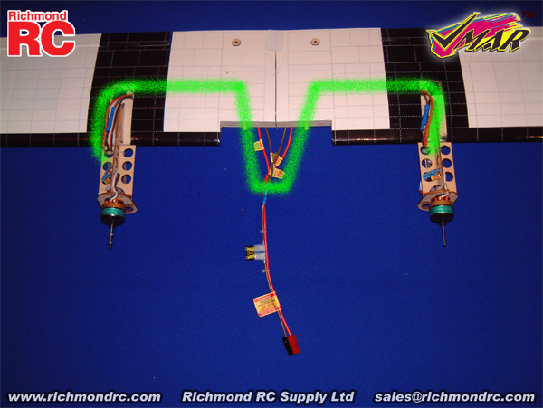
c) Read all labels attached to the Power Wiring Harness. See Figure 3A and the green "path" as a reference to guide you as you proceed with the installation.
|
|
|
3A - Power Wiring Harness Installed - Viewed from Top Side of Wing
|
d) Turn the wing upright so that you can see the large access cavity in the center of the wing where you have installed your ESC's. Support the wing with a sheet of foam rubber or folded up fluffy towel.
e) Position the wing so that the trailing edge (thin) is closer to you and the leading edge (thick) is further away. When oriented in this manner, the wing panel on your left will be the left wing panel in flight and the wing panel on your right will be the right wing panel in flight. This consistent definition of left and right makes it much easier to install the Power Wiring Harness properly.
f) Connect the end of the red Power Wiring Harness marked "+ Power + Positive Left" to the left wing speed control Red (+) power lead.
g) Connect the end of the black Power Wiring Harness marked "- Power - Negative Left" to the left wing speed control Black (-) power lead.
h) This completes the wiring of power to the left wing speed control. Now follow a similar process for the right wing speed control.
f) Connect the end of the red Power Wiring Harness marked "+ Power + Positive Right" to the right wing speed control Red (+) power lead.
g) Connect the end of the black Power Wiring Harness marked "- Power - Negative Right" to the right wing speed control Black (-) power lead.
h) This completes the wiring of power to the right wing and left wing speed controls. Now connect the wiring for the fuselage speed control.
i) Connect the end of the red Power Wiring Harness marked "+ Power + Positive Fuselage" to the fuselage speed control Red (+) lead.
j) Connect the end of the black Power Wiring Harness marked "- Power - Negative Fuselage" to the fuselage speed control Black (-) power lead.
k) Once completed, the left and right speed control and motor assemblies and the fuselage speed control and motor will be connected to the Power Wiring Harness. Separate the quick connect joint (located between the two white zip straps) so that the wing wiring and harness can be removed from the fuselage with the wing.
l) Do NOT plug in your battery pack until you are ready to fly or test your equipment. The battery pack should NOT be plugged in when the model is unattended and should NOT be plugged in when transporting your model in a vehicle.
|
| 1.3.1.4.4. Stage 4 - Install Flap Wiring Harness (WHF) - For VMA-J210X JU52 Trimotor |
a) Review the Read Me First documentation and the Assembly and Operations Manual that came with your model. Complete Stage 1 and Stage 2 from the Assembly and Operations Manual. Once completed you will have assembled the wing.
b) Review Stage 13 from the Assembly and Operations Manual. Pay particular attention to the larger warning label and note the color conventions used for different manufacturers. This will be important when you plug in your servos and when you plug into your receiver. Locate the Flap Wiring Harness parts bag and remove the harness.
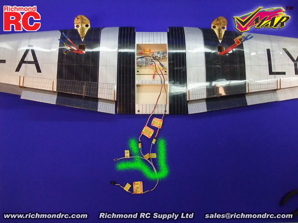
c) Read all labels attached to the Flap Wiring Harness. See Figure 4A and the green "path" as a reference to guide you as you proceed with the installation.
|
|
|
4A - Flap Wiring Harness Installed - Viewed from Top Side of Wing
|
d) Turn the wing upright so that you can see the large access cavity near the center of the wing. Support the wing with a sheet of foam rubber or folded up fluffy towel.
e) Position the wing so that the trailing edge (thin) is closer to you and the leading edge (thick) is further away. When oriented in this manner, the wing panel on your left will be the left wing panel in flight and the wing panel on your right will be the right wing panel in flight. This consistent definition of left and right makes it much easier to install the flap servos and flap wiring harness properly.
f) Thread the end of the wire marked "Flap Servo Left" through the left side of the large access cavity near the center of the wing and through the internal wiring access tube to the left flap servo cavity located about 8.5 in. (215 mm) outboard from the center of the wing. Pull the loose end of the wire out of the tube so that it exits the downward facing bottom surface of the wing through the left flap servo cavity. Connect the left flap servo to this wire. Use the supplied "Flap Left" sticker to wrap the connection securely. Gently pull the wire back from the source and install the left flap servo into position as shown in Stage 13 of the Assembly & Operations Manual.
g) Repeat this process for the wire marked "Flap Servo Right", working from the right side of the large access cavity near the center of the wing and the internal wiring access tube that runs to the right servo cavity. Connect the right flap servo to this wire. Use the supplied "Flap Right" sticker to wrap the connection securely. Gently pull the wire back from the source and install the right flap servo into position as shown in Stage 13 of the Assembly & Operations Manual.
h) Once completed, both flap servos will be installed into the bottom of the wing and the end of the Flap Wiring Harness that is labeled "Flap Channel ==> ==>" will be hanging loose near the center of the wing ready to be plugged into the flap channel of your receiver.
|
| 1.3.1.5. Support | On Line, eMail, Fax, Phone, Mail
|
| We offer the Best in Support Services. | We back up our products and our customers with the best support services available. From our industry leading Knowledge Base to information about your Shipment, we've got you covered!
To access our Support Services please:
Your Choice of Support Services that Work for You:
|
| 1.3.1.5.1. Contact Us | For Sales and other Inquiries
|
| Support - Contact Us - Reach our Sales Department by eMail, Fax, Phone or Mail | Technical Inquiries: Please review the information provided in our Knowledge Base. After checking our Knowledge Base, if you need further assistance please use our Submit A Question service to get a response within 2 Business Days. Sales Inquiries: Please note that our Sales Department personnel are trained and dedicated to:
- Helping you with non-technical pre-purchase questions,
- Helping you place your order,
- Pointing out any sales, combos or specials that you may wish to consider,
- Inputting your order to our computer system so that it ships out as accurately and quickly as possible... usually the same day,
- Resolving any invoicing problems, and
- Helping to sort out any missing shipment or shipment damage issues.
Their depth of technical knowledge is about on par with what is shown in our printed sales literature. In most cases, they are working from the same printed advertisements or content from our web site that you are. Asking sales personnel to confirm the size, color and availability of a product is well within their capabilities. However, asking detailed questions about technical issues is not.
Buy our Products:
For All Other Inquiries... please consult the following resources:
- On Line Information
- On Line Support Services
- After reviewing our On Line resources, if you require additional assistance please contact us by eMail, fax, phone or mail as follows:
- Ask a Question
- eMail
- Fax
- Phone
- Mail
- Richmond RC Supply Ltd, #114 - 7350 72nd Street, Delta, BC, V4G-1H9
- Mail & printed correspondence only.
- We are not able to accomodate personal site visits or drop-offs/pick-ups at this location.
- Please note that all inbound Shipments require pre-Authorization in advance.
- Unauthorized inbound shipments will be refused.
|
| 1.3.1.6. Keep Up to Date | Check Frequently for Updates |
| Support - Stay Current - Check Frequently for Updated &/or Additional Information | This information is subject to change without notice. When viewing this information in a printed form the printing date will be visible in the lower right corner. Check frequently for updates &/or Additional Information.at www.richmondrc.com, > Enter the Site, > Support Services, follow the links to our Knowledge Base. Review the Table of Contents and search for the name and/or part number of this product.
For automated notification of changes to information contained in our Knowledge Base please register as a Priority Response member and subscribe to our Priority Response Notification Service.
|
| 1.3.2. Wiring Harness Set - For VMA-J210X JU52 Trimotor - Additional Information | In general "Additional" Information is:
- In addition to that found in other documentation related to this product,
- Often reflects feedback &/or questions from users of the product.
Subject to the Conditions of Use, please review the attachments and related articles listed below.
|
| COPYRIGHT | Copyright Richmond RC Supply Ltd. All rights reserved.
|
| 1.4. Wiring Harness Set - For VMA-T210X Twin Otter |
| 1.4.1. Wiring Harness Set - #VMA-T210XWHS For VMA-T210X Twin Otter - READ ME FIRST | PLEASE READ ME FIRST
BEFORE PROCEEDING TO ASSEMBLE OR OPERATE THIS PRODUCT
|
| LIABILITY DISCLAIMER & COPYRIGHT NOTICE | LIABILITY DISCLAIMER
The authors and/or suppliers and/or disseminaters of this information and/or product expressly disclaim any warranties or representations, either expressed or implied, including but not limited to implied warranties of fitness, accuracy, timeliness or applicability of the information and/or product provided here. In no event will the authors and/or suppliers and/or disseminaters of this information and/or product have any obligation arising from contract or tort, for loss of revenue or profit, or for indirect, special, incidental, consequential or other damages of any sort arising from this information and/or product. In using this information and/or product, the user accepts all responsibility for and all liability associated with such use.
PROCEEDING WITH THE USE OF THIS INFORMATION AND/OR PRODUCT INDICATES AGREEMENT WITH AND ACCEPTANCE OF THE LIABILITY DISCLAIMER.
|
| Please Note the following Caution | CAUTION
A Remote Control (RC) model aircraft is not a toy. It is a flying model that functions much like a full size airplane. If you do not assemble and operate model aircraft properly you can cause injury to yourself and others and damage property. DO NOT FLY a model aircraft unless you are qualified.
You are ultimately responsible for the mechanical, aeronautical and electrical integrity of any model you fly and all of the components that make up the model including but not limited to the airframe itself, control surfaces, hinges, linkages, covering, engine, motor, radio, servos, switches, wiring, battery and parts. Check all components before and after each flight. It is essential that you act with the clear understanding that you are solely responsible for all aspects of the model at all times. DO NOT FLY until it is right.
|
| 1.4.1.1. Wiring Harness Set - For VMA-T210X Twin Otter - General Information | |
|
| COPYRIGHT | Copyright Richmond RC Supply Ltd. All rights reserved.
|
| Tips for Avoiding Common Problems |
We have supplied thousands and thousands and thousands of model aircraft in the past 20 plus years. We're not bragging! We tell you this to give some credibility to our suggested list of tips that follow. In talking to modelers around the world, here is what we have found is the key to...
AVOIDING 90% of PROBLEMS that can arise:
- READ THE CAUTION ABOVE & READ THE LIABILITY DISCLAIMER.You are responsible for all aspects of any model you fly. You're It!
- READ ALL DOCUMENTATION before doing anything else!
- INSPECT CAREFULLY immediately upon arrival!.
- RETAIN ALL PACKAGING until the checkout is complete! If you need to return anything you must have all of the original packaging.
- READ & LOOK! At everything! Do it once & then do it again.
- REMEMBER WHAT "ARF" STANDS FOR. ARF means ALMOST Ready to Fly with an emphasis on ALMOST! Some assembly and modeling skills are required.
- ALLOW ENOUGH TIME to enjoy the assembly process! Rushing into a 6 hour job with 3 hours to spare simply will not work. This is a Hobby... take your time.
- DRY FIT & TEST ASSEMBLE EVERYTHING before you glue anything!
- USE 30 MINUTE EPOXY when joining wings & installing stabilizers and other structural components but only after you have dry fitted and test assembled the components without glue! Once parts are glued together they cannot be unglued and they cannot be returned or replaced without charge.
- PLAN AHEAD! BE CAREFUL! If you get into trouble, DON'T PANIC. Review everything again, talk it over with an experienced modeler and if still in difficulty consult our Support Services.
- TEST TEST!!! TUG TUG TUG!!! EVERYTHING... BEFORE & AFTER EACH FLIGHT! Your model may have been largely pre-constructed and may have pre-installed control rods, hinges, control surfaces and many other essential components. Hinges may have been pinned after they have been installed. However, you must double check every control surface and component before and after each flight. You and only you are responsible for the integrity of all components and the integrity of the model itself. Check everything before and after each flight. Tug on control surfaces, control rods, mounting bolts, T-nuts, mounting plates... tug on everything!
- DO NOT OVER TIGHTEN WING BOLTS or other fasteners. You want bolts and nuts snugly tight and if metal you can use a medium grade thread locker such as Pacer Z42 to help them stay tight. Fasteners must be snug and secure. However a model airplane is not a farm tractor or a garbage compactor. You do not need a pipe wrench or an electric drill to tighten up wing bolts or any other fastener. Leave your plumbing and power tools at home.. hand tools only and go easy on the torque... snug and secure... not stripped or torqued until they squeak or break. Wing bolts can take tremendous torque before breaking... but when you over tighten them or use an electric screw driver on a set of wing bolts, long before the bolts break you can fracture the fuselage, crack the mounting blocks or pull the heads of the bolts through the wing... these problems have a nasty habit of revealing themselves when you least expect the wing to fall off!
- DO NOT OVERPOWER ANY MODEL! Stay within the recommended power range for the model. If you overpower the model you run a high risk of structural failure that will lead to loss of control and a subsequent crash that will destroy the model and may cause injury and/or property damage.
- ASSUME NOTHING! Remember the old yarn about what happens when you ASS-U-ME something. Check everything repeatedly and frequently and DO NOT FLY any model unless you are satisfied that everything is in good working order.
|
| 1.4.1.2. Wiring Harness Set - For VMA-T210X Twin Otter - Introduction | |
Before beginning the Installation Instructions please read the Overview and check off the components provided. Each component is in a labelled parts bag. Please check off the components against the Contents list below. Leave the components in their parts bags for now. Do not remove the components from their parts bags until each is needed during the installation process.
|
| Wiring Harness Sets - For VMAR Power Packs - Overview | VMAR Wiring Harness Sets for VMAR Power Packs contain all of the wiring and connectors to install and operate the components of multi-motor VMAR Power Packs and any servos included with the power pack. ( Note: Single motor power systems include discrete wiring components and do not use a wiring harness "set" per se.)
VMAR Wiring Harness Sets are factory designed to fit into the applicable VMAR model with its applicable VMAR power system and any included servos. All of the connectors have been factory installed.
VMAR Wiring Harness Sets are:
- Included with VMAR Power Packs for the applicable model.
- Available as a stand alone accessory for use with VMAR Power Modules for the applicable model.
- Provide for fast and reliable installation of VMAR Power Packs and Power Modules into VMAR multi-motor electric models.
- Note: Modelers who are not experienced with multi-motor electric flight systems are strongly encouraged to use the VMAR Wiring Harness Set applicable to their VMAR multi-motor model. Scratch building and installing a reliable wiring harness set for a multi-motor electric model requires approximately 8 hours of work & considerable knowledge and experience.
- May be suitable for use with some third party power systems and servos supplied by end users.
|
| 1.4.1.3. Wiring Harness Set - For VMA-T210X Twin Otter - Contents | This VMAR Wiring Harness Set (WHS) contains the following
- Aileron Wiring Harness (WHA) to connect the two aileron servos in the wings to the aileron channel of the receiver in the fuselage. Total Length = approx 15 in. (380mm). Length from aileron channel connector to Y = approx 4 in. (102 mm)
- (Note: The aileron wiring harness does NOT provide for flaperon operation using a computer radio and two discrete receiver channels. VMAR models utilizing two aileron servos will usually support computer radio flaperon functionality in conjunction with the aileron wiring harness if additional aileron extensions are purchased in addition to the aileron wiring harness included with the wiring harness set).
- Throttle Wiring Harness (WHT) to connect two Electronic Speed Controls (ESC) to the throttle channel of the receiver in the fuselage. Total Length = approx 13 in. (330mm). Length from throttle channel connector to Y = approx 7 in. (178 mm)
- Power Wiring Harness (WHP) to provide Positive (+) and Negative (-) power to two motors from a single battery (fused in line). Total Length = approx 22.5 in. (570mm). Length from battery connector to Y = approx 9.25 in. (235 mm)
This VMAR Wiring Harness Set also contains:
- Elevator Wiring Harness (WHE) to connect the elevator servo located near the tail to the elevator channel of the receiver in the fuselage. Total Length = approx 23.5 in. (597 mm). Length from elevator channel connector to junction = approx 7 in. (178 mm)
- Rudder & Steering Wiring Harness (WHR) to connect the rudder servo located near the tail and the nose wheel steering servo to the rudder channel of the receiver in the fuselage. Total Length = approx 23.5 in. (597 mm). Length from rudder channel connector to Y = approx 7 in. (178 mm).
-
End User Wiring Labels
|
| 1.4.1.4. Wiring Harness Set - For VMA-T210X Twin Otter - Installation Instructions | |
Consult any labels carefully, particularly the larger WARNING labels. The labels are largely self explanatory. Reading the labels will save you a great deal of time and help prevent damage to your equipment.
|
| 1.4.1.4.1. Stage 1 - Install Aileron Wiring Harness (WHA) - For VMA-T210X Twin Otter |
a) Review the Read Me First documentation and the Assembly and Operations Manual that came with your model. Complete Stage 0 from the Read Me First document and Stage 1 from the Assembly and Operations Manual. Once completed you will have assembled the wing.
b) After assembly of the wing you may install the Aileron Wiring Harness. Locate the Aileron Wiring Harness parts bag and remove the harness.
c) Read all labels attached to the Aileron Wiring Harness. Use 1A and the green "path" as a reference to guide you as you proceed with the installation.
|
|
|
1A - Aileron Wiring Harness Installed - Viewed from Bottom Side of Wing
|
d) Turn the wing on its back so that you can see the two square access holes near the center of the wing. Support the center of the underside of the wing with a sheet of foam rubber or folded up fluffy towel.
e) Position the inverted wing so that the leading edge (thick) is closer to you and the trailing edge (thin) is further away. When oriented in this manner, the inverted wing panel on your left will be the left wing panel in flight and the inverted wing panel on your right will be the right wing panel in flight. This consistent definition of left and right makes it much easier to install the aileron servos and aileron wiring harness properly.
f) Thread the end of the wire marked "Aileron Servo Left" through the left square access hole near the center of the wing and through the internal wiring access tube to the left aileron servo cavity located about 8.5 in. (215 mm) outboard from the center of the wing. Pull the loose end of the wire out of the tube so that it exits the upward facing bottom surface of the wing through the left servo cavity. Connect the left aileron servo to this wire. Use the supplied "Aileron Left" sticker to wrap the connection securely. Gently pull the wire back from the source and install the left aileron servo into position as shown in Stage 2 of the Assembly & Operations Manual.
g) Repeat this process for the wire marked "Aileron Servo Right", working with the right square access hole near the center of the wing and the internal wiring access tube that runs to the right servo cavity. Connect the right aileron servo to this wire. Use the supplied "Aileron Right" sticker to wrap the connection securely. Gently pull the wire back from the source and install the right aileron servo into position as shown in Stage 2 of the Assembly & Operations Manual.
h) Once completed, both aileron servos will be installed into the bottom of the wing and the end of the Aileron Wiring Harness that is labeled "Aileron Channel ==> ==>" will be hanging loose near the center of the wing ready to be plugged into the aileron channel of your receiver.
|
| 1.4.1.4.2. Stage 2 - Install Throttle Wiring Harness (WHT) - For VMA-T210X Twin Otter |
a) Review the Read Me First documentation and the Assembly and Operations Manual that came with your model. Complete Stage 9 from the Assembly and Operations Manual using either a VMAX Power Module set, a VMAX Power Pack or third party motors and speed controllers.
b) After installation of your motors and speed controllers you may install the Throttle Warning Harness. Locate the Throttle Wiring Harness parts bag and remove the harness.
c) Read all labels attached to the Throttle Wiring Harness. Use 2A and the green "path" as a reference to guide you as you proceed with the installation.
|
|
|
2A - Throttle Wiring Harness Installed - Viewed from Top Side of Wing
|
d) Turn the wing on its back so that you can see the two square access holes near the center of the wing. Support the center of the underside of the wing with a sheet of foam rubber or folded up fluffy towel.
e) Position the inverted wing so that the leading edge (thick) is closer to you and the trailing edge (thin) is further away. When oriented in this manner, the inverted wing panel on your left will be the left wing panel in flight and the inverted wing panel on your right will be the right wing panel in flight. This consistent definition of left and right makes it much easier to install the Throttle Wiring Harness properly.
f) Thread the red, white and black wire lead from the left speed control into the power access cavity located on the downward facing surface of the left wing about 8.5 in. (215 mm) outboard from the center of the wing. Continue feeding the red, white and black wire from the cavity into and though the internal wiring access tube that runs to the left square access hole in the center of the wing. Gently pull the wire so that it protrudes from the left square access hole. Connect this protruding wire to the end of the Throttle Wire Harness marked "Throttle Control Left". Use the supplied "Throttle Left" sticker to wrap the connection securely.
g) Repeat this process for the right wing. Thread the red, white and black wire lead from the right speed control into the power access cavity located on the downward facing surface of the right wing about 8.5 in. (215 mm) outboard from the center of the wing. Continue feeding the red, white and black wire from the cavity into and though the internal wiring access tube that runs to the right square access hole in the center of the wing. Gently pull the wire so that it protrudes from the right square access hole. Connect this protruding wire to the end of the Throttle Wire Harness marked "Throttle Control Right". Use the supplied "Throttle Right" sticker to wrap the connection securely.
h) Once completed, both electronic speed controls will be connected to the Throttle Wiring Harness and the end of the Throttle Wiring Harness that is labeled "Throttle Channel ==> ==>" will be hanging loose near the center of the wing ready to be plugged into the throttle channel of your receiver.
|
| 1.4.1.4.3. Stage 3 - Install Power Wiring Harness (WHP) - For VMA-T210X Twin Otter |
a) Review the Read Me First documentation and the Assembly and Operations Manual that came with your model. Complete Stage 9 from the Assembly and Operations Manual using either a VMAX Power Module set, a VMAX Power Pack or third party motors and speed controllers.
b) After installation of your motors and speed controllers you may install the Power Wiring Harness. Locate the Power Wiring Harness parts bag and remove the harness.
c) Read all labels attached to the Power Wiring Harness. Use 3A and the green "path" as a reference to guide you as you proceed with the installation.
|
|
|
3A - Power Wiring Harness Installed - Viewed from Top Side of Wing
|
d) Turn the wing on its back so that you can see the two square access holes near the center of the wing. Support the center of the underside of the wing with a sheet of foam rubber or folded up fluffy towel.
e) Position the inverted wing so that the leading edge (thick) is closer to you and the trailing edge (thin) is further away. When oriented in this manner, the inverted wing panel on your left will be the left wing panel in flight and the inverted wing panel on your right will be the right wing panel in flight. This consistent definition of left and right makes it much easier to install the Power Wiring Harness properly.
f) Thread the end of the wire marked "+ Power + Positive Left" through the left square access hole near the center of the wing and through the internal wiring access tube to the left power access cavity located about 8.5 in. (215 mm) outboard from the center of the wing. Pull the loose end of the wire out of the tube so that it exits the downward facing surface of the wing through the left power access cavity. Connect the left speed control Red (+) lead to this wire. Gently pull the wire back from the source while routing the connected Red wire so that it lies neatly from the speed control and into the left power access cavity.
g) Repeat this process for the negative power connection to the left speed control. Thread the end of the wire marked "- Power - Negative Left" through the left square access hole near the center of the wing and through the internal wiring access tube to the left power access cavity located about 8.5 in. (215 mm) outboard from the center of the wing. Pull the loose end of the wire out of the tube so that it exits the downward facing surface of the wing through the left power access cavity. Connect the left speed control Black (-) lead to this wire. Gently pull the wire back from the source while routing the connected Black wire so that it lies neatly from the speed control and into the left power access cavity.
h) This completes the wiring of power to the left speed control.
i) Now follow a similar process for the right speed control. Thread the end of the wire marked "+ Power + Positive Right" through the right square access hole near the center of the wing and through the internal wiring access tube to the right power access cavity located about 8.5 in. (215 mm) outboard from the center of the wing. Pull the loose end of the wire out of the tube so that it exits the downward facing surface of the wing through the right power access cavity. Connect the right speed control Red (+) lead to this wire. Gently pull the wire back from the source while routing the connected Red wire so that it lies neatly from the speed control and into the right power access cavity.
j) Repeat this process for the negative power connection to the right speed control. Thread the end of the wire marked "- Power -Negative Right" through the right square access hole near the center of the wing and through the internal wiring access tube to the right power access cavity located about 8.5 in. (215 mm) outboard from the center of the wing. Pull the loose end of the wire out of the tube so that it exits the downward facing surface of the wing through the right power access cavity. Connect the right speed control Black (-) lead to this wire. Gently pull the wire back from the source while routing the connected Black wire so that it lies neatly from the speed control and into the right power access cavity.
k) Once completed, the left and right speed control and motor assemblies will be connected to the Power Wiring Harness and the end of Power Wiring Harness with the square-like Black and Red connector will be hanging loose near the center of the wing ready to be plugged into your LiPo battery pack.
|
| 1.4.1.4.4. Stage 4 - Install Elevator Wiring Harness (WHE) - For VMA-T210X Twin Otter |
a) Review the Read Me First documentation and the Assembly and Operations Manual that came with your model. Complete Stage 12 from the Assembly and Operations Manual up to the point where your elevator servo is ready to install into the fuselage as illustrated in 12D.
b) Locate the Elevator Wiring Harness parts bag and remove the harness.
c) Read all labels attached to the Elevator Wiring Harness.
d) Remove the top hatch from the fuselage. Working from within the fuselage, pass the end of the wire labeled "Elevator Servo ==> ==>" back into the tail section of the fuselage and out through the elevator servo cavity on the right side of the fuselage near the tail.
e) Gently pull the wire so that it protrudes from the elevator servo cavity. Connect this protruding wire to the elevator servo. Use the supplied "Elevator" sticker to wrap the connection securely.
f) Working from within the fuselage gently pull the Elevator Wiring Harness forward toward the front of the fuselage and install the elevator servo into position as illustrated in picture 12E of the Assembly and Operations Manual.
g) Once completed, the elevator servo will be connected to the Elevator Wiring Harness and the end of the Elevator Wiring Harness that is labeled "Elevator Channel ==> ==>" will be hanging loose near the center of the fuselage ready to be plugged into the elevator channel of your receiver.
|
| 1.4.1.4.5. Stage 5 - Install Rudder & Steering Wiring Harness (WHR) - For VMA-T210X Twin Otter |
a) Review the Read Me First documentation and the Assembly and Operations Manual that came with your model. Complete Stage 12 from the Assembly and Operations Manual up to the point where your rudder servo is ready to install (but not yet installed) into the fuselage as illustrated in 12F.
b) Locate the Rudder & Steering Wiring Harness parts bag and remove the harness.
c) Read all labels attached to the Rudder & Steering Wiring Harness.
d) Remove the top hatch from the fuselage. Working from within the fuselage, pass the end of the wire labeled "Rudder Servo ==> ==>" back into the tail section of the fuselage and out through the rudder servo cavity on the left side of the fuselage near the tail.
e) Gently pull the wire so that it protrudes from the rudder servo cavity. Connect this protruding wire to the rudder servo. Use the supplied "Rudder" sticker to wrap the connection securely.
f) Working from within the fuselage gently pull the Rudder & Steering Wiring Harness forward toward the front of the fuselage and install the rudder servo into position as illustrated in picture 12F of the Assembly and Operations Manual.
g) Working from within the fuselage connect the wire "Nose Servo ==> ==>" to the nose gear steering servo as illustrated in pictures 20B, 20C and 21.2 of the Assembly and Operations Manual. Use the supplied "Steering" sticker to wrap the connection securely.
h) Once completed, the rudder servo and the nose gear servo will be connected to the Rudder & Steering Wiring Harness and the end of the Rudder & Steering Wiring Harness that is labeled "Rudder Channel ==> ==>" will be hanging loose near the center of the fuselage ready to be plugged into the rudder channel of your receiver.
|
| 1.4.1.5. Support | On Line, eMail, Fax, Phone, Mail
|
| We offer the Best in Support Services. | We back up our products and our customers with the best support services available. From our industry leading Knowledge Base to information about your Shipment, we've got you covered!
To access our Support Services please:
Your Choice of Support Services that Work for You:
|
| 1.4.1.5.1. Contact Us | For Sales and other Inquiries
|
| Support - Contact Us - Reach our Sales Department by eMail, Fax, Phone or Mail | Technical Inquiries: Please review the information provided in our Knowledge Base. After checking our Knowledge Base, if you need further assistance please use our Submit A Question service to get a response within 2 Business Days. Sales Inquiries: Please note that our Sales Department personnel are trained and dedicated to:
- Helping you with non-technical pre-purchase questions,
- Helping you place your order,
- Pointing out any sales, combos or specials that you may wish to consider,
- Inputting your order to our computer system so that it ships out as accurately and quickly as possible... usually the same day,
- Resolving any invoicing problems, and
- Helping to sort out any missing shipment or shipment damage issues.
Their depth of technical knowledge is about on par with what is shown in our printed sales literature. In most cases, they are working from the same printed advertisements or content from our web site that you are. Asking sales personnel to confirm the size, color and availability of a product is well within their capabilities. However, asking detailed questions about technical issues is not.
Buy our Products:
For All Other Inquiries... please consult the following resources:
- On Line Information
- On Line Support Services
- After reviewing our On Line resources, if you require additional assistance please contact us by eMail, fax, phone or mail as follows:
- Ask a Question
- eMail
- Fax
- Phone
- Mail
- Richmond RC Supply Ltd, #114 - 7350 72nd Street, Delta, BC, V4G-1H9
- Mail & printed correspondence only.
- We are not able to accomodate personal site visits or drop-offs/pick-ups at this location.
- Please note that all inbound Shipments require pre-Authorization in advance.
- Unauthorized inbound shipments will be refused.
|
| 1.4.1.6. Keep Up to Date | Check Frequently for Updates |
| Support - Stay Current - Check Frequently for Updated &/or Additional Information | This information is subject to change without notice. When viewing this information in a printed form the printing date will be visible in the lower right corner. Check frequently for updates &/or Additional Information.at www.richmondrc.com, > Enter the Site, > Support Services, follow the links to our Knowledge Base. Review the Table of Contents and search for the name and/or part number of this product.
For automated notification of changes to information contained in our Knowledge Base please register as a Priority Response member and subscribe to our Priority Response Notification Service.
|
| 1.4.2. Wiring Harness Set - For VMA-T210X Twin Otter - Additional Information | In general "Additional" Information is:
- In addition to that found in other documentation related to this product,
- Often reflects feedback &/or questions from users of the product.
Subject to the Conditions of Use, please review the attachments and related articles listed below. |
| COPYRIGHT | Copyright Richmond RC Supply Ltd. All rights reserved.
|
|