| 1. VMA-D260X Dornier DO27 45-61 ARF ECS - Supplement to the Manual |
| COPYRIGHT |
Copyright Richmond RC Supply Ltd. All rights reserved.
|
| 1.1. VMA-D260X Dornier DO27 45-61 ARF ECS - Ailerons and Flaps - Locations |
This supplementary information applies to manuals with a copyright date of 20030321 (see back cover). Manuals having later copyright dates may already reflect this supplementary information. Please note that this model has ailerons located outboard on the wings and flaps located inboard on the wings. The ailerons are activated by a servo in the bottom of each wing. The flaps are optional and will require two servos located in the more inboard wing cavities. |
| 1.2. VMA-D260X Dornier DO27 45-61 ARF ECS - Control Horns |
|
| Control Horn Installation - How to |
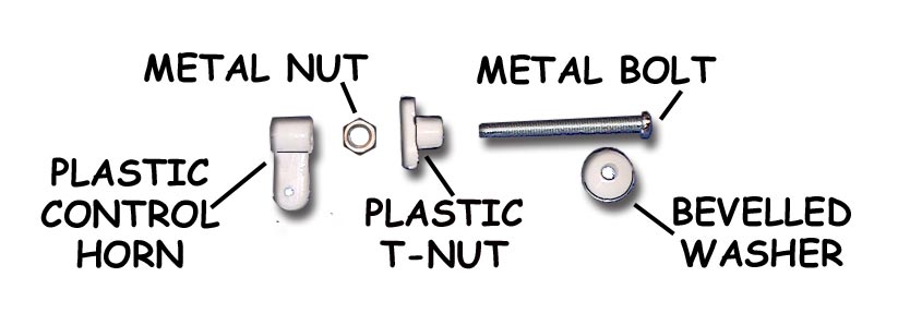
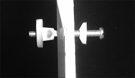
Question: How are VMAR control horns installed? The iillustration below and to the left shows a control horn set before installation. Note 5 parts make up the set. In Light Duty applications the Metal Nut may not be included and only 4 parts will make up the set. The illustration below and to the right shows a control horn set partially installed. Although illustrations in various manuals show the bevelled washer with the bevel pointing away from the surface we find that we get a cleaner strong installation with the bevel pointing inwards. We recommend wicking thin CA such as Pacer ZAP/CA (Pink) into the exposed wood surrounding the hole in the control surface. This helps further strengthen the wood. This is not a requirement but if you are pushing the power limits or planning on extreme aerobatics or speeds, the extra strength could come in handy. Use two applications of thin CA 1 minute apart, BEFORE installing the control horn.
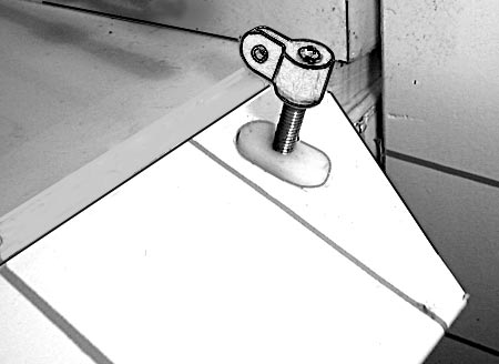
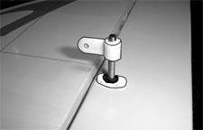
The illustration below shows horn side view of a control horn set fully installed. The illustration to the left is a lighter duty application without the metal nut. The illustration to the right shows a heavier duty application with the metal nut installed. If the metal nuts have been supplied with the horns, we recommend using them.
|
| 1.3. VMA-D260X Dornier DO27 45-61 ARF ECS - Cowl - Handle Carefully |
This supplementary information applies to manuals with a copyright date of 20030321 (see back cover). Manuals having later copyright dates may already reflect this supplementary information. Please handle the cowl carefully. The cowl has been pre-painted to match the appearance of the full size aircraft that this model has been based upon. The shape of the cowl will be most realistic when fitted over the firewall.
|
| 1.4. VMA-D260X Dornier DO27 45-61 ARF ECS - Engine & Prop Size - Recommendations |
This supplementary information applies to manuals with a copyright date of 20030321 (see back cover). Manuals having later copyright dates may already reflect this supplementary information. This model flies well on a .46 size two stroke engine such as the VMAX 46PRO or a .52 size two stroke engine such as the VMAX 52PRO. We suggest using a larger diameter lower pitch prop that you might have used on another model with a similar sized engine. Check your engine manual and select a prop that is at the maximum diameter in the recommended range of props for your engine. We have found that a .46 works well on this model with an 11 x 5 or 12 x 4 prop. The idea here is to locate the thrust out beyond the edge of the fuselage and cowl. A larger diameter prop helps accomplish this.
|
| 1.5. VMA-D260X Dornier DO27 45-61 ARF ECS - Fuel Tank Installation - Page 9 & 10, Stage 18 |
This supplementary information applies to manuals with a copyright date of 20030321 (see back cover). Manuals having later copyright dates may already reflect this supplementary information. Please see Page 4, Stage 5, Figures 5.1 and 5.2 Some servos have a rubber boot strain relief around the wire coming from the servo. Notch the bottom of the servo rails shown in Figures 5.1 and 5.2 to clear the rubber root or wire if required.
|
| 1.6. VMA-D260X Dornier DO27 45-61 ARF ECS - Long Servo Arm - Page 4 & 5, Stage 5 & 6 |
This supplementary information applies to manuals with a copyright date of 20030321 (see back cover). Manuals having later copyright dates may already reflect this supplementary information. Please see Page 4 & 5, Stage 5 & 6,
Use a long servo arm and mount the servo as close to the servo cover plate as possible to maximize the length of the servo arm protruding from the bottom of the wing.
|
| 1.7. VMA-D260X Dornier DO27 45-61 ARF ECS - Servo Boot Clearance - Page 4, Stage 5, Figure 5.1 & 5.2 |
This supplementary information applies to manuals with a copyright date of 20030321 (see back cover). Manuals having later copyright dates may already reflect this supplementary information. Please see Page 4, Stage 5, Figures 5.1 and 5.2 Some servos have a rubber boot strain relief around the wire coming from the servo. Notch the bottom of the servo rails shown in Figures 5.1 and 5.2 to clear the rubber root or wire if required.
|
| 1.8. VMA-D260X Dornier DO27 45-61 ARF ECS - Servo Cover Plates - Aileron & Flaps - Page 4 & 5, Stage 5 & 6 |
This supplementary information applies to manuals with a copyright date of 20030321 (see back cover). Manuals having later copyright dates may already reflect this supplementary information. Please see Page 4, Stage 5, Figures 5.1 and 5.2 Some servos have a rubber boot strain relief around the wire coming from the servo. Notch the bottom of the servo rails shown in Figures 5.1 and 5.2 to clear the rubber root or wire if required.
|
| 1.9. VMA-D260X Dornier DO27 45-61 ARF ECS - Trim Pieces - Test before Cleaning |
This supplementary information applies to manuals with a copyright date of 20030321 (see back cover). Manuals having later copyright dates may already reflect this supplementary information. The factory has supplied a number of trim pieces. Many of these pieces such as the chin blocks on either side of the fuselage near the cowl and the spats on the main landing gear legs have been pre-applied and painted with epoxy paint. Always test these painted surfaces for compatibitliy with any fuels, solvents or cleaning solutions. Review and follow our recommendations regarding cleaning your model.
|