1. Wiring Harness Set - For VMA-T210X Twin Otter - Installation Instructions
 
 
Consult any labels carefully, particularly the larger WARNING labels. The labels are largely self explanatory. Reading the labels will save you a great deal of time and help prevent damage to your equipment.
 
 
1.1. Stage 1 - Install Aileron Wiring Harness (WHA) - For VMA-T210X Twin Otter
 
a) Review the Read Me First documentation and the Assembly and Operations Manual that came with your model. Complete Stage 0 from the Read Me First document and Stage 1 from the Assembly and Operations Manual. Once completed you will have assembled the wing.
 
b) After assembly of the wing you may install the Aileron Wiring Harness.  Locate the Aileron Wiring Harness parts bag and remove the harness.
 
c) Read all labels attached to the Aileron Wiring Harness. Use 1A and the green "path" as a reference to guide you as you proceed with the installation.
 

1A - Aileron Wiring Harness Installed - Viewed from Bottom Side of Wing

 
d) Turn the wing on its back so that you can see the two square access holes near the center of the wing. Support the center of the underside of the wing with a sheet of foam rubber or folded up fluffy towel.
 
e) Position the inverted wing so that the leading edge (thick) is closer to you and the trailing edge (thin) is further away. When oriented in this manner, the inverted wing panel on your left will be the left wing panel in flight and the inverted wing panel on your right will be the right wing panel in flight. This consistent definition of left and right makes it much easier to install the aileron servos and aileron wiring harness properly.
 
f) Thread the end of the wire marked "Aileron Servo Left" through the left square access hole near the center of the wing and through the internal wiring access tube to the left aileron servo cavity located about 8.5 in. (215 mm) outboard from the center of the wing. Pull the loose end of the wire out of the tube so that it exits the upward facing bottom surface of the wing through the left servo cavity. Connect the left aileron servo to this wire. Use the supplied "Aileron Left" sticker to wrap the connection securely. Gently pull the wire back from the source and install the left aileron servo into position as shown in Stage 2 of the Assembly & Operations Manual.
 
g) Repeat this process for the wire marked "Aileron Servo Right", working with the right square access hole near the center of the wing and the internal wiring access tube that runs to the right servo cavity. Connect the right aileron servo to this wire. Use the supplied "Aileron Right" sticker to wrap the connection securely. Gently pull the wire back from the source and install the right aileron servo into position as shown in Stage 2 of the Assembly & Operations Manual.
 
h) Once completed, both aileron servos will be installed into the bottom of the wing and the end of the Aileron Wiring Harness that is labeled "Aileron Channel ==> ==>" will be hanging loose near the center of the wing ready to be plugged into the aileron channel of your receiver.
 
1.2. Stage 2 - Install Throttle Wiring Harness (WHT) - For VMA-T210X Twin Otter
a) Review the Read Me First documentation and the Assembly and Operations Manual that came with your model. Complete Stage 9 from the Assembly and Operations Manual using either a  VMAX Power Module set, a VMAX Power Pack or third party motors and speed controllers. 
 
b) After installation of your motors and speed controllers you may install the Throttle Warning Harness.  Locate the Throttle Wiring Harness parts bag and remove the harness.
 
c) Read all labels attached to the Throttle Wiring Harness. Use 2A and the green "path" as a reference to guide you as you proceed with the installation.
 

2A - Throttle Wiring Harness Installed - Viewed from Top Side of Wing


d) Turn the wing on its back so that you can see the two square access holes near the center of the wing. Support the center of the underside of the wing with a sheet of foam rubber or folded up fluffy towel.
 
e) Position the inverted wing so that the leading edge (thick) is closer to you and the trailing edge (thin) is further away. When oriented in this manner, the inverted wing panel on your left will be the left wing panel in flight and the inverted wing panel on your right will be the right wing panel in flight. This consistent definition of left and right makes it much easier to install the Throttle Wiring Harness properly.
 
f) Thread the red, white and black wire lead from the left speed control into the power access cavity located on the downward facing surface of the left wing about 8.5 in. (215 mm) outboard from the center of the wing. Continue feeding the red, white and black wire from the cavity into and though the internal wiring access tube that runs to the left square access hole in the center of the wing. Gently pull the wire so that it protrudes from the left square access hole. Connect this protruding wire to the end of the Throttle Wire Harness marked "Throttle Control Left". Use the supplied "Throttle Left" sticker to wrap the connection securely.
 
g) Repeat this process for the right wing. Thread the red, white and black wire lead from the right speed control into the power access cavity located on the downward facing surface of the right wing about 8.5 in. (215 mm) outboard from the center of the wing. Continue feeding the red, white and black wire from the cavity into and though the internal wiring access tube that runs to the right square access hole in the center of the wing. Gently pull the wire so that it protrudes from the right square access hole. Connect this protruding wire to the end of the Throttle Wire Harness marked "Throttle Control Right". Use the supplied "Throttle Right" sticker to wrap the connection securely.
 
h) Once completed, both electronic speed controls will be connected to the Throttle Wiring Harness and the end of the Throttle Wiring Harness that is labeled "Throttle Channel ==> ==>" will be hanging loose near the center of the wing ready to be plugged into the throttle channel of your receiver.  
 
 
1.3. Stage 3 - Install Power Wiring Harness (WHP) - For VMA-T210X Twin Otter
 
a) Review the Read Me First documentation and the Assembly and Operations Manual that came with your model. Complete Stage 9 from the Assembly and Operations Manual using either a  VMAX Power Module set, a VMAX Power Pack or third party motors and speed controllers. 
 
b) After installation of your motors and speed controllers you may install the Power Wiring Harness.  Locate the Power Wiring Harness parts bag and remove the harness.
 
c) Read all labels attached to the Power Wiring Harness. Use 3A and the green "path" as a reference to guide you as you proceed with the installation.
 

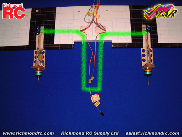
3A - Power Wiring Harness Installed - Viewed from Top Side of Wing

 
d) Turn the wing on its back so that you can see the two square access holes near the center of the wing. Support the center of the underside of the wing with a sheet of foam rubber or folded up fluffy towel.
 
e) Position the inverted wing so that the leading edge (thick) is closer to you and the trailing edge (thin) is further away. When oriented in this manner, the inverted wing panel on your left will be the left wing panel in flight and the inverted wing panel on your right will be the right wing panel in flight. This consistent definition of left and right makes it much easier to install the Power Wiring Harness properly.
 
f) Thread the end of the wire marked "+ Power + Positive Left" through the left square access hole near the center of the wing and through the internal wiring access tube to the left power access cavity located about 8.5 in. (215 mm) outboard from the center of the wing. Pull the loose end of the wire out of the tube so that it exits the downward facing surface of the wing through the left power access cavity. Connect the left speed control Red (+) lead to this wire. Gently pull the wire back from the source while routing the connected Red wire so that it lies neatly from the speed control and into the left power access cavity.
 
g) Repeat this process for the negative power connection to the left speed control.  Thread the end of the wire marked "- Power - Negative Left" through the left square access hole near the center of the wing and through the internal wiring access tube to the left power access cavity located about 8.5 in. (215 mm) outboard from the center of the wing. Pull the loose end of the wire out of the tube so that it exits the downward facing surface of the wing through the left power access cavity. Connect the left speed control Black (-) lead to this wire. Gently pull the wire back from the source while routing the connected Black wire so that it lies neatly from the speed control and into the left power access cavity.
 
h) This completes the wiring of power to the left speed control.
 
i) Now follow a similar process for the right speed control. Thread the end of the wire marked "+ Power + Positive Right" through the right square access hole near the center of the wing and through the internal wiring access tube to the right power access cavity located about 8.5 in. (215 mm) outboard from the center of the wing. Pull the loose end of the wire out of the tube so that it exits the downward facing surface of the wing through the right power access cavity. Connect the right speed control Red (+) lead to this wire. Gently pull the wire back from the source while routing the connected Red wire so that it lies neatly from the speed control and into the right power access cavity.
 
j) Repeat this process for the negative power connection to the right speed control.  Thread the end of the wire marked "- Power -Negative Right" through the right square access hole near the center of the wing and through the internal wiring access tube to the right power access cavity located about 8.5 in. (215 mm) outboard from the center of the wing. Pull the loose end of the wire out of the tube so that it exits the downward facing surface of the wing through the right power access cavity. Connect the right speed control Black (-) lead to this wire. Gently pull the wire back from the source while routing the connected Black wire so that it lies neatly from the speed control and into the right power access cavity.
 
k) Once completed, the left and right speed control and motor assemblies will be connected to the Power Wiring Harness and the end of Power Wiring Harness with the square-like Black and Red connector will be hanging loose near the center of the wing ready to be plugged into your LiPo battery pack.
 
 
1.4. Stage 4 - Install Elevator Wiring Harness (WHE) - For VMA-T210X Twin Otter

a) Review the Read Me First documentation and the Assembly and Operations Manual that came with your model. Complete Stage 12 from the Assembly and Operations Manual up to the point where your elevator servo is ready to install into the fuselage as illustrated in 12D.
 
b) Locate the Elevator Wiring Harness parts bag and remove the harness.
 
c) Read all labels attached to the Elevator Wiring Harness.

d) Remove the top hatch from the fuselage. Working from within the fuselage, pass the end of the wire labeled "Elevator Servo ==> ==>" back into the tail section of the fuselage and out through the elevator servo cavity on the right side of the fuselage near the tail.
 
e) Gently pull the wire so that it protrudes from the elevator servo cavity. Connect this protruding wire to the elevator servo. Use the supplied "Elevator" sticker to wrap the connection securely.
 
f) Working from within the fuselage gently pull the Elevator Wiring Harness forward  toward the front of the fuselage and install the elevator servo into position as illustrated in picture 12E of the Assembly and Operations Manual.  
 
g) Once completed, the elevator servo will be connected to the Elevator Wiring Harness and the end of the Elevator Wiring Harness that is labeled "Elevator Channel ==> ==>" will be hanging loose near the center of the fuselage ready to be plugged into the elevator channel of your receiver.  
 
1.5. Stage 5 - Install Rudder & Steering Wiring Harness (WHR) - For VMA-T210X Twin Otter

a) Review the Read Me First documentation and the Assembly and Operations Manual that came with your model. Complete Stage 12 from the Assembly and Operations Manual up to the point where your rudder servo is ready to install (but not yet installed) into the fuselage as illustrated in 12F.
 
b) Locate the Rudder & Steering Wiring Harness parts bag and remove the harness.
 
c) Read all labels attached to the Rudder & Steering Wiring Harness.

d) Remove the top hatch from the fuselage. Working from within the fuselage, pass the end of the wire labeled "Rudder Servo ==> ==>" back into the tail section of the fuselage and out through the rudder servo cavity on the left side of the fuselage near the tail.
 
e) Gently pull the wire so that it protrudes from the rudder servo cavity. Connect this protruding wire to the rudder servo. Use the supplied "Rudder" sticker to wrap the connection securely.
 
f) Working from within the fuselage gently pull the Rudder & Steering Wiring Harness forward  toward the front of the fuselage and install the rudder servo into position as illustrated in picture 12F of the Assembly and Operations Manual.  
 
g) Working from within the fuselage connect the wire "Nose Servo ==> ==>" to the nose gear steering servo as illustrated in pictures 20B, 20C and 21.2 of the Assembly and Operations Manual. Use the supplied "Steering" sticker to wrap the connection securely.
 
h) Once completed, the rudder servo and the nose gear servo will be connected to the Rudder & Steering Wiring Harness and the end of the Rudder & Steering Wiring Harness that is labeled "Rudder Channel ==> ==>" will be hanging loose near the center of the fuselage ready to be plugged into the rudder channel of your receiver.