ArticlesArticles Most Popular ArticlesMost Popular Articles Most Helpful ArticlesMost Helpful Articles Submit A QuestionSubmit A Question Login for PRIORITY RESPONSELogin for PRIORITY RESPONSE
RSS Feeds
DrillDown Icon Table of Contents
DrillDown Icon LIABILITY & COPYRIGHT
DrillDown Icon Site Information
DrillDown Icon * Support
DrillDown Icon Technical Info - Adhesives
DrillDown Icon Technical Info - Master Airscrew
DrillDown Icon Technical Info - POLYPRO
DrillDown Icon Technical Info - RC Flying - General
DrillDown Icon Technical Info - RC Flying Electric - General
DrillDown Icon Technical Info - ULTRA POWER Technology - Products
DrillDown Icon Technical Info - VMAR - General
DrillDown Icon VMAR - Documents
DrillDown Icon + READ ME FIRST - POLYCOTE ECS MODELS
DrillDown Icon + READ ME FIRST - VCOTE MODELS
DrillDown Icon General Information
DrillDown Icon * Manual Supplement
DrillDown Icon * Important Information
DrillDown Icon * Support
DrillDown Icon Stay Current - Check Frequently
DrillDown Icon + READ ME FIRST - VCOTE2 MODELS
DrillDown Icon VMAR - Adhesives
DrillDown Icon VMAR - Canopy (Window) Cleaning
DrillDown Icon VMAR - Canopy (Window) Replacement
DrillDown Icon VMAR - CG Location - General
DrillDown Icon VMAR - Cleaning Model Aircraft
DrillDown Icon VMAR - Construction
DrillDown Icon VMAR - Control Surfaces
DrillDown Icon VMAR - Covering
DrillDown Icon VMAR - Cowl Installation
DrillDown Icon VMAR - Electric Power Conversions
DrillDown Icon VMAR - Engine Mounting
DrillDown Icon VMAR - Engine Power Module
DrillDown Icon VMAR - Flaps & Flaperons
DrillDown Icon VMAR - Fuel Leaks - Fuselage Soaked - What now?
DrillDown Icon VMAR - Fuel Proofing
DrillDown Icon VMAR - Fuel Tanks
DrillDown Icon VMAR - Glow Power Conversions
DrillDown Icon VMAR - Hardware & Fittings
DrillDown Icon VMAR - Jet (Turbine) Power Conversions
DrillDown Icon VMAR - Landing Gear
DrillDown Icon VMAR - Packaging
DrillDown Icon VMAR - Parts
DrillDown Icon VMAR - Servo Trays
DrillDown Icon VMAR - Specifications of Models
DrillDown Icon VMAR - Wings
DrillDown Icon VMAR - Wing Fairing Replacement
DrillDown Icon VMAR - Wood Types Used
DrillDown Icon Technical Info - VMAR - Products
DrillDown Icon Technical Info - VMAX Electric Power Systems - General
DrillDown Icon Technical Info - VMAX Electric Power Systems - Products
DrillDown Icon Technical Info - VMAX Engines (Glow) - General
DrillDown Icon Technical Info - VMAX Engines (Glow) - Products
  Email This ArticlePrint PreviewPrint Current Article/Category and All Sub-Articles/Categories
 
VMA ARF Products - Supplement to the Manual


Control Horn Installation - How to

Question: How are VMAR control horns installed? 

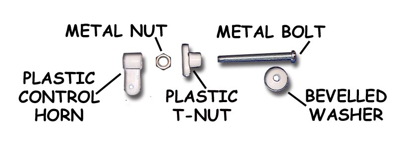
Answer: VMAR control horns are unique. They work better and are easier to install. They do not look like most of the control horns you have seen before and you may not recognize them for what they are or you may think they are missing. They are in the control horn parts bag &/or wing parts bag  inside the master bag of hardware and consist of a metal bolt, metal nut, beveled white plastic washer, a white plastic T-nut and the white plastic control horn itself that connects to a clevis or rod.

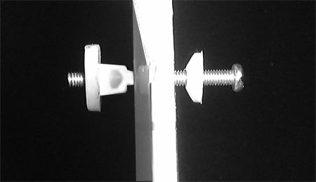
The iillustration below and to the left shows a control horn set before installation. Note 5 parts make up the set. In Light Duty applications the Metal Nut may not be included and only 4 parts will make up the set. The illustration below and to the right shows a control horn set partially installed. Although illustrations in various manuals show the bevelled washer with the bevel pointing away from the surface we find that we get a cleaner strong installation with the bevel pointing inwards.

We recommend wicking thin CA such as Pacer ZAP/CA (Pink) into the exposed wood surrounding the hole in the control surface. This helps further strengthen the wood. This is not a requirement but if you are pushing the power limits or planning on extreme aerobatics or speeds, the extra strength could come in handy. Use two applications of thin CA 1 minute apart, BEFORE installing the control horn.

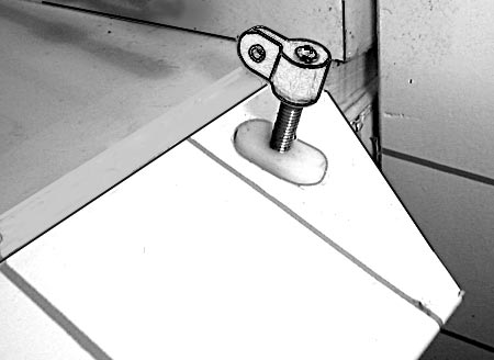
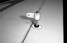
The illustration below shows horn side view of a control horn set fully installed. The illustration to the left is a lighter duty application without the metal nut. The illustration to the right shows a heavier duty application with the metal nut installed. If the metal nuts have been supplied with the horns, we recommend using them.  

Article ID: 4511