a) Review the Read Me First documentation and the Assembly and Operations Manual that came with your model. Complete Stage 0 from the Read Me First document and Stage 1 from the Assembly and Operations Manual. Once completed you will have assembled the wing.
b) After assembly of the wing you may install the Aileron Wiring Harness. Locate the Aileron Wiring Harness parts bag and remove the harness.
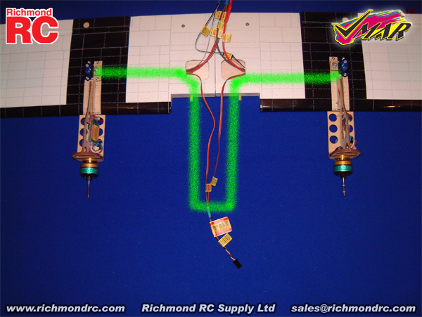
c) Read all labels attached to the Aileron Wiring Harness. Use 1A and the green "path" as a reference to guide you as you proceed with the installation.
|
|
|
1A - Aileron Wiring Harness Installed - Viewed from Bottom Side of Wing
|
d) Turn the wing on its back so that you can see the two square access holes near the center of the wing. Support the center of the underside of the wing with a sheet of foam rubber or folded up fluffy towel.
e) Position the inverted wing so that the leading edge (thick) is closer to you and the trailing edge (thin) is further away. When oriented in this manner, the inverted wing panel on your left will be the left wing panel in flight and the inverted wing panel on your right will be the right wing panel in flight. This consistent definition of left and right makes it much easier to install the aileron servos and aileron wiring harness properly.
f) Thread the end of the wire marked "Aileron Servo Left" through the left square access hole near the center of the wing and through the internal wiring access tube to the left aileron servo cavity located about 8.5 in. (215 mm) outboard from the center of the wing. Pull the loose end of the wire out of the tube so that it exits the upward facing bottom surface of the wing through the left servo cavity. Connect the left aileron servo to this wire. Use the supplied "Aileron Left" sticker to wrap the connection securely. Gently pull the wire back from the source and install the left aileron servo into position as shown in Stage 2 of the Assembly & Operations Manual.
g) Repeat this process for the wire marked "Aileron Servo Right", working with the right square access hole near the center of the wing and the internal wiring access tube that runs to the right servo cavity. Connect the right aileron servo to this wire. Use the supplied "Aileron Right" sticker to wrap the connection securely. Gently pull the wire back from the source and install the right aileron servo into position as shown in Stage 2 of the Assembly & Operations Manual.
h) Once completed, both aileron servos will be installed into the bottom of the wing and the end of the Aileron Wiring Harness that is labeled "Aileron Channel ==> ==>" will be hanging loose near the center of the wing ready to be plugged into the aileron channel of your receiver.
|