| 1. Technical Information - VMAR - Product by Product |
| 1.1. VMA-A0026 Avenger 60 ARF Aerobatic Pattern |
| 1.1.1. VMA-A0026 Avenger 60 ARF Aerobatic Pattern - READ ME FIRST |
| READ ME FIRST - for Models with VCOTE Covering |
The Read Me First for models covered with VCOTE applies to this product and is available at:
The Read Me First will open in a second window. Please review it, print it or email it using the icons located near the top right of the Read Me First page (mouse over each icon for feedback about what it does). When you are finished, close the Read Me First window and continue browing here.
|
| 1.1.2. VMA-A0026 Avenger 60 ARF Aerobatic Pattern - Additional Information |
In general "Additional" Information is:
Subject to the Conditions of Use, please review the attachments and related articles listed below. |
| COPYRIGHT |
Copyright Richmond RC Supply Ltd. All rights reserved.
|
| 1.1.2.1. VMA-A0026 Avenger 60 ARF Aerobatic Pattern - Rear Exhaust & Tuned Pipe |
Question: I have a VMA-A0026 Avenger 60 ARF Aerobatic Pattern. Can I use an engine with a rear exhaust and a tuned pipe?
Answer: The VMA-A0026 Avenger 60 ARF Aerobatic Pattern was designed assuming a side exhaust and standard muffler. You will likely need to make many changes to the factory engine compartment and mount to accomodate a rear exhaust engine and depending on the engine this may not be possible at all. Tuned pipes that are exposed and attach to the side of the fuselage may be possible however the Avenger was not designed with tuned pipes in mind.
|
| 1.1.3. VMA-A0026 Avenger 60 ARF Aerobatic Pattern - Assembly & Operations Manual in PDF format |
| 1.2. VMA-A460X A4 Skyhawk Jet (Prop) 45-52 ARF 3DS - Blue & Navy |
| 1.2.1. VMA-A460X A4 Skyhawk Jet (Prop) 45-52 ARF 3DS - READ ME FIRST |
| READ ME FIRST - for Models with VCOTE2 - 3DS Covering |
The Read Me First for models covered with VCOTE2 - 3DS applies to this product and is available at:
The Read Me First will open in a second window. Please review it, print it or email it using the icons located near the top right of the Read Me First page (mouse over each icon for feedback about what it does). When you are finished, close the Read Me First window and continue browing here.
|
| 1.2.2. VMA-A460X A4 Skyhawk Jet (Prop) 45-52 ARF 3DS - Assembly & Operations Manual in PDF format |
| 1.3. VMA-A140X Apache III 40 ARF ECS Trainer 69"- Various Colors |
| 1.3.1. VMA-A140X Apache III 40 ARF ECS Trainer 69" - READ ME FIRST |
| READ ME FIRST - for Models with POLYCOTE ECS Covering |
The Read Me First for models covered with POLYCOTE ECS applies to this product and is available at:
The Read Me First will open in a second window. Please review it, print it or email it using the icons located near the top right of the Read Me First page (mouse over each icon for feedback about what it does). When you are finished, close the Read Me First window and continue browing here.
|
| 1.3.2. VMA-A140X Apache III 40 ARF ECS Trainer 69" - Additional Information |
In general "Additional" Information is:
Subject to the Conditions of Use, please review the attachments and related articles listed below. |
| COPYRIGHT |
Copyright Richmond RC Supply Ltd. All rights reserved.
|
| 1.3.2.1. VMA-A140X Apache III 40 ARF ECS Trainer 69" - Control Horns - How Many in Parts Bag? |
Question: The assembly manual for my Apache refers to five control horn sets. The parts bag contains only 3 sets in total and I think I only need 3 sets. Is this correct? Answer: Yes only three control horn sets are required for your Apache. One control horn is used for the rudder and two control horns are used for the elevators. |
| 1.3.2.2. VMA-A140X Apache III 40 ARF ECS Trainer 69" - Engine Clamp Bolts - How to Remove |
Question: I want to completely remove the engine clamp bolts from the engine mount in my Apache III. How do I do this? Answer: This is not difficult but if it is necessary, there are two ways to approach this.
|
| 1.3.2.3. VMA-A140X Apache III 40 ARF ECS Trainer 69" - Fuel Tank - How to install |
Question: How do I install the Fuel Tank into my VMAR Apache III? Answer: This is not difficult but the instruction book does not cover this directly. Remove the fuel compartment hatch from the bottom of the fuselage. Remove the black sealing gasket from the fuel tank. Apply sealant such as Pacer Dap-A-Goo to the front face of the tank around the neck and re-install the gasket. Apply more sealant to the front face of the gasket. Insert the tank into the fuel tank compartment with the tubes forward and oriented so that the bottom of the tank is positioned correctly. Press the tank firmly against the back side of the firewall and secure in place while the sealant cures. Reinstall the fuel tank compartment hatch to the bottom of the fuselage. |
| 1.3.2.4. VMA-A140X Apache III 40 ARF ECS Trainer 69" - Landing Gear Location - Instructions Wrong |
Some copies of the the Apache III Instruction Manual may have typo errors as follows: |
| 1.3.2.5. VMA-A140X Apache III 40 ARF ECS Trainer 69" - Landing Gear - Steering Arm does not fit |
| Consumer called and advised his steering arm does not fit into the Apache III nose gear. The do fit but requires careful alignment and a bit of up pressure and twisting motion of the nose gear to insert into the steering arm bearing in some cases. To make this a bit easier the modeler can either drill out the steering arm bearing a bit, or grind the end of the nose gear wire a bit or sand a bit of plastic off the back of the steering arm bearing holder. |
| 1.3.2.6. VMA-A140X Apache III 40 ARF ECS Trainer 69" - Rudder Control Horn Hole - Wrong Location |
Some versions of the Apache III may have been shipped with the rudder control horn mounting hole drilled too low. The rudder control horn mounting hole is pre-drilled at the factory prior to the rudder being covered. The hole is about .25” (6mm) in diameter and is located just aft of the rudder hinge line towards the bottom of the rudder. The hole can be located by holding the vertical stabilizer and rudder assembly and backlighting it from behind. A limited number of Apache III’s produced in the fall of 2003 and shipped to market in the Nov 2003 through Spring 2004 time frame may have the hole drilled about 1.25”(31mm) too low. Resolution. In Brief: Drill a new hole for the rudder control horn approximately 1.25” (31mm) higher than the hole pre-drilled at the factory. In Detail: Insert the vertical stabilizer and rudder assembly into the mounting slot in the top of the fuselage. Locate the rudder control rod protruding from the top of the aft end of the fuselage. Free the rudder control rod from any lockdown tape installed near the servo tray for shipping purposes. From the aft end of the fuselage, extend the rudder control rod until it reaches the rudder hinge line. The rod should be approximately in line with the rudder control horn hole. If it is not, mark where the control rod crosses the rudder hinge line. Remove the vertical stabilizer from the fuselage. Drill a new rudder control horn hole to align with the control rod. Drill the hole to be the same diameter as that of the incorrectly placed hole done by the factory. Install the rudder control horn assembly in the new hole per the instruction procedures in the manual. |
| 1.3.2.7. VMA-A140X Apache III 40 ARF ECS Trainer 69" - Wing Servo Arm contacting Pilot Figure |
Question: The servo arm on my wing servo is contacting the head of the pilot figure in my Apache III. Is this normal? What should I do to fix it? Answer: No this is not what we intended and it should be fixed before flying your model. There are a couple of ways to resolve this. 1) Make sure your servo is a standard servo and that it is mounted down on the rails properly. Some of the ball bearing and high torque servos are in a case that stands higher than a standard servo. 2) Orient the servo so that the output shaft and arm are closer to the trailing edge of the wing rather than the leading edge. Adjust the aileron control rod lengths accordingly. 3) If after checking on 1 and 2, your servo arm is still contacting the pilot figure you will need to go to a lower profile servo or move the pilot figure slightly. We recommend moving the pilot figure and/or mounting plate... it's relatively simple to do. Here are three options that more or less accomplish the same thing:
|
| 1.3.3. VMA-A140X Apache III 40 ARF ECS Trainer 69" - Assembly & Operations Manual in PDF format |
| 1.4. VMA-A340X Arrow Tiger 46-52 ARF ECS SPORT AEROBATIC - Various Colors |
| 1.4.1. CG Location - Instructions Wrong - VMA-A340X VMAR Arrow Tiger 46-52 ARF ECS |
The CG location in the Instruction Book for the VMAR Arrow Tiger may be incorrect in some printings. Instructions that give the CG location at 3-1/8" to 3-3/8" are incorrect. |
| 1.4.2. Hovering - Is It Possible for the VMA-A340X VMAR Arrow Tiger to Hover? |
Question: Can the VMA Arrow Tiger 46-52 ARF be made to Hover? Answer: No. Better Answer: The Arrow Tiger was designed with knife edge and high speed in mind. Hovering was not in the design criteria. In theory almost anything with a power to weight ratio greater than 1 can be made to Hover. Give the weight of the Arrow Tiger and power of a typical 46 to 52 it is not possible to Hover the Arrow Tiger. |
| 1.4.3. Instructions - Wrong Model Named - VMA-A340X VMAR Arrow Tiger 46-52 ARF ECS - Hornet means Arrow Tiger |
| There are various references to the VMAR Hornet in the instruction book for the VMAR Arrow Tiger. References to the VMAR Hornet in the instruction book for the VMAR Arrow Tiger are misprints. All references to the VMAR Hornet are intended to refer to the VMAR Arrow Tiger. |
| 1.4.4. VMA-A340X Arrow Tiger 46-52 ARF - Is it a pattern ship? |
Question: Is the VMA Arrow Tiger 46-52 ARF considered a pattern ship? Answer: No not really. The Arrow Tiger is a hot moving sport plane that is very aerobatic, does knife edge and many other maneuvers but it was not designed with pattern flying in mind. In could be used a stepping stone moving towards a pattern airplane such as the VMAR Avenger 60 ARF. |
| 1.4.5. ZBO-Y190604A More Information | ||||||||||||||||||
More Information about #ZBO-Y190604A ... BLOWOUT - VMAR ARROW TIGER 46-52 ARF - FINAL SALE This is a BLOWOUT... FINAL SALE item and the following caution applies:
No other information is available regarding #ZBO-Y190604A BLOWOUT - VMAR ARROW TIGER 46-52 ARF - FINAL SALE. |
| 1.5. VMA-BS110 Balsa Stripper |
| 1.5.1. VMA-BS110 - What type of Blade does the unit use? |
Question: What type of blade is used in the VMAR Balsa Stripper? I want to have some spares in case the factory blade gets dull or breaks. Answer: The VMAR Balsa Stipper uses standard #11 Blades. |
| 1.6. VMA-B140X Beaver 45-60 Semiscale ARF ECS - Various Colors |
| 1.6.1. VMA-B140X - Assembly & Operations Manual in PDF format |
| 1.6.2. VMA-B140X - Landing Gear (Main) - Fibreglass or Aluminum? |
Question: Does the VMAR Beaver 45-60 ARF come with fibreglass or aluminum main gear?
Answer: During mid 2006 the VMAR Beaver 45-60 ARF main landing gear was upgraded from fibreglass to T6 aluminum main gear. The new main gear is lighter and stronger than that used earlier.
|
| 1.6.3. VMA-B140X - Wing Spars - Aluminum (VMA_B140XSPR) Size |
Question: I have one of the new VMAR Beaver 45-60 ARF's with plug in wings. What size are the wing spar tubes? They appear to be aluminum.
Answer: The VMAR Beaver 45-60 was upgraded in 2006 to include a plug in wing. The wing is joined and mated to the fuselage using two aluminum tubes. The tube sizes are as follows:
1) Long Tube: 22.9 in. (582 mm) long x .43 in. (11 mm) OD
2) Short Tube: 11.4 in. (289 mm) long x .43 in. (11 mm) OD
|
| 1.6.4. VMA-B140X - Weight of Beaver 45-60 with VMAR Floats |
Question: I am planning a project using the VMAR Beaver 45-60 ARF on the VMAR 35" Floats. What would be the weight of the Beaver plus floats? I qm considering different power systems and radio gear, so please tell me the weight of the model plus floats without any engine or radio gear. Answer: The weight of the VMAR Beaver 45-60 ARF equipped with VMAR 35" Floats is approx 5 lbs 9 oz [2530 grams]. This includes the weight of the cowl and a typical propeller but without any power system or radio gear. |
| 1.7. VMA-B160C Beaver 60-90 Semiscale ARF |
| 1.7.1. VMA-B160C Beaver 60-90 Semiscale ARF - READ ME FIRST |
| READ ME FIRST - for Models with POLYCOTE ECS Covering |
The Read Me First for models covered with POLYCOTE ECS applies to this product and is available at:
The Read Me First will open in a second window. Please review it, print it or email it using the icons located near the top right of the Read Me First page (mouse over each icon for feedback about what it does). When you are finished, close the Read Me First window and continue browing here.
|
| 1.7.2. VMA-B160C Beaver 60-90 Semiscale ARF - Assembly & Operations Manual in PDF format |
| 1.7.3. ZBO-Y190702A More Information | ||||||||||||||||||||
More Information about #ZBO-Y190702A ... BLOWOUT - VMAR BEAVER 60-90 SEMISCL ARF FINAL SALE This is a BLOWOUT... FINAL SALE item and the following caution applies:
No other information is available regarding #ZBO-Y190702A BLOWOUT - VMAR BEAVER 60-90 SEMISCL ARF FINAL SALE
|
| 1.8. VMA-B191C Beaver 120+ ARF SemiScale ARF 120 in. Span |
| 1.8.1. VMA-B191C Beaver 120+ ARF SemiScale ARF 120 in. Span - READ ME FIRST |
| READ ME FIRST - for Models with POLYCOTE ECS Covering |
The Read Me First for models covered with POLYCOTE ECS applies to this product and is available at:
The Read Me First will open in a second window. Please review it, print it or email it using the icons located near the top right of the Read Me First page (mouse over each icon for feedback about what it does). When you are finished, close the Read Me First window and continue browing here.
|
| 1.8.2. VMA-B191C Beaver 120+ ARF SemiScale ARF 120 in. Span - Additional Information |
In general "Additional" Information is:
Subject to the Conditions of Use, please review the attachments and related articles listed below. |
| COPYRIGHT |
Copyright Richmond RC Supply Ltd. All rights reserved.
|
| 1.8.2.1. VMA-B191C Beaver 120+ ARF SemiScale ARF 120 in. Span - Aileron Extensions - Not Provided |
Question: My assembly manual for the 10 foot Beaver #VMA-B191C makes reference to some aileron extensions. I did not get these. What's the story? Am I missing something? Answer: Due to the wide variation in radio connectors, servos and tolerance for different lengths of extensions we have discontinued supplying aileron extensions. Modelers should follow their radio manufacturers recommendations regarding the use of aileron extensions. |
| 1.8.2.2. VMA-B191C Beaver 120+ ARF SemiScale ARF 120 in. Span - Instructions Do Not Reflect Plug In Wing |
The Beaver 120ARF has been updated to incorporate a plug-in semi-symmetrical wing. Some of the screws, washers etc in the instruction book are no longer included as they are no longer needed. The wooden spar joiner has been replaced by two long round aluminum tubes that mount the wings to the fuselage. The CG Location has not changed. The CG is as stated and is approx coincident with the thickest part of the wing about 30% back from the leading edge. |
| 1.8.2.3. VMA-B190C Beaver 120+ ARF SemiScale ARF 120 in. Span - Older Version Without Tube Spars |
The attached PDF contains important information about the original older version of the B190C Beaver 120ARF that had wood spar joiners and the wing located in a saddle in the top of the fuselage. This older model was superceded in 2004-2005 by the new B191C Beaver 120ARF that has two aluminum tube spars and a fuselage that is used with "plug in" wings. |
| 1.8.3. VMA-B191C Beaver 120+ ARF SemiScale ARF 120 in. Span - Assembly & Operations Manual in PDF format |
| 1.9. VMA-B210X Bird Dog 06-12 ARF - Elect & Glow - Various Colors |
| 1.9.1. VMA-B210X Bird Dog 06-12 ARF - READ ME FIRST |
PLEASE READ ME FIRST BEFORE PROCEEDING TO ASSEMBLE OR OPERATE THIS PRODUCT
|
| LIABILITY DISCLAIMER & COPYRIGHT NOTICE |
LIABILITY DISCLAIMER The authors and/or suppliers and/or disseminaters of this information and/or product expressly disclaim any warranties or representations, either expressed or implied, including but not limited to implied warranties of fitness, accuracy, timeliness or applicability of the information and/or product provided here. In no event will the authors and/or suppliers and/or disseminaters of this information and/or product have any obligation arising from contract or tort, for loss of revenue or profit, or for indirect, special, incidental, consequential or other damages of any sort arising from this information and/or product. In using this information and/or product, the user accepts all responsibility for and all liability associated with such use. PROCEEDING WITH THE USE OF THIS INFORMATION AND/OR PRODUCT INDICATES AGREEMENT WITH AND ACCEPTANCE OF THE LIABILITY DISCLAIMER.
|
| Please Note the following Caution |
CAUTION A Remote Control (RC) model aircraft is not a toy. It is a flying model that functions much like a full size airplane. If you do not assemble and operate model aircraft properly you can cause injury to yourself and others and damage property. DO NOT FLY a model aircraft unless you are qualified. You are ultimately responsible for the mechanical, aeronautical and electrical integrity of any model you fly and all of the components that make up the model including but not limited to the airframe itself, control surfaces, hinges, linkages, covering, engine, motor, radio, servos, switches, wiring, battery and parts. Check all components before and after each flight. It is essential that you act with the clear understanding that you are solely responsible for all aspects of the model at all times. DO NOT FLY until it is right.
|
| 1.9.1.1. VMA-B210X Bird Dog 06-12 ARF - General Information |
|
| COPYRIGHT |
Copyright Richmond RC Supply Ltd. All rights reserved.
|
| Tips for Avoiding Common Problems |
We have supplied thousands and thousands and thousands of model aircraft in the past 20 plus years. We're not bragging! We tell you this to give some credibility to our suggested list of tips that follow. In talking to modelers around the world, here is what we have found is the key to... AVOIDING 90% of PROBLEMS that can arise:
|
| 1.9.1.2. VMA-B210X Bird Dog 06-12 ARF - Supplement to the Manual |
| COPYRIGHT |
Copyright Richmond RC Supply Ltd. All rights reserved.
|
| 1.9.1.2.1. VMA-B210X Bird Dog 06-12 ARF - Battery Installation |
This supplementary information applies to manuals with a copyright date of 20050712 (see back cover). Manuals having later copyright dates may already reflect this supplementary information. Please see Page 16, Figure 28B. The text below the Caption for Figure 28B refers to "...with Velcro (supplied) or ..." Please note that Bird Dogs produced prior to August 2005 did not come with Velcro and the battery should be secured using lightweight foam so that it does not move. Beginning with production in September 2005, a new laser cut battery platform and Velcro retaining strap was included along with an ADDITIONAL INFORMATION sheet that explains how to install the battery platform. The ADDITIONAL INFORMATION sheet supercedes the manual.
|
| 1.9.1.2.2. VMA-B210X Bird Dog 06-12 ARF - Control Horns |
This supplementary information applies to manuals with a copyright date of 20050712 (see manual back cover). Manuals having later copyright dates may already reflect this supplementary information. Some Bird Dogs produced prior to August 2005, were shipped with two small plastic disc's in lieu of a single square backing plate for some of the control horns. These small disc's serve exactly the same purpose as the square backing plate... the only difference is that there are two of them... one for each screw. Beginning with production in September 2005, a new laser cut control horn assembly replaced the plastic screw type control horns previously used with the VMAR Bird Dog 06-12 ARF. If laser cut control horns have been supplied, an ADDITIONAL INFORMATION sheet has been included with the control horn parts bag and shows the correct method of installing the laser cut control horns. The ADDITIONAL INFORMATION sheet supercedes the manual.
|
| 1.9.1.2.3. VMA-B210X Bird Dog 06-12 ARF - Firewall Spacing - Page 8, Figure 12K |
This supplementary information applies to manuals with a copyright date of 20050712 (see back cover). Manuals having later copyright dates may already reflect this supplementary information. Please see Page 8, Figure 12K. This figure shows the 3mm nuts evenly spaced at .875 in. (22 mm) from the firewall. This works well for some motor shafts but may be lessened or expanded to reflect different lengths of motor shafts. The important thing here is that the motor shaft be able to extend through the front of the cowl and still securely hold the propeller without the propeller contacting the cowl. A distance of 1-3/32 in. (27mm) works well for many popular motors.
|
| 1.9.1.2.4. VMA-B210X Bird Dog 06-12 ARF - Vertical Stabilizer Fit - Page 6, Step 8.1 & Figure 8A |
This supplementary information applies to manuals with a copyright date of 20050712 (see back cover). Manuals having later copyright dates may already reflect this supplementary information. Please see Page 6, Step 8.1 & Figure 8A. Step 8.1 and Figure 8A describe and show the dry test fitting of the vertical stabilizer into the vertical stabilizer slot in the top of the fuselage. On some early versions of the Bird Dog produced in July and August of 2005 the slot in the fuselage is slightly too deep so that the vertical stabilizer tab shown in Figure 8D does not contact the bottom of the slot when inserted into the fuselage. If your vertical stabilizer does not contact the bottom of the fuselage slot when inserted into the fuselage you need to rectify this with a small filler strip inserted into the fuselage slot and tacked into place with CA or other glue before installing the vertical stabilizer using 30 minute epoxy. The filler strip should be approximately 5-7mm high and the width and length of the slot. Use balsa or other light wood to make this strip. Dry fit the strip and the vertical stabilizer before gluing anything into place. The idea here is to make sure that the bottom of the vertical stabilizer tab seats firmly against the strip which in turn fills the gap in the bottom of the fuselage slot. |
| 1.9.1.3. VMA-B210X Bird Dog 06-12 ARF - Important Information |
| 1.9.1.3.1. VMA-B210X Bird Dog 06-12 ARF - Covering |
This model uses POLYCOTE ECS Covering |
| POLYCOTE ECS - Care & Maintenance - Quick Tips |
|
Question: Do you have any pointers regarding the Care & Maintenance of POLYCOTE ECS? Answer: Yes we have this Summary of Quick Tips. See www.richmondrc.com ( Enter Site > Support Services > Knowledge Base then Search on "Covering") for an expanded explanation of each Tip. Polyester offers the best in covering performance and as with any new modern technology, the maintenance methods may be different than those you used with your older covering. This is NOT Monokote or Solarfilm, its different. If you have used ORACOVER or ULTRACOTE you will have some experience with working with POLYESTER as a covering material. Here is our Summary of Quick Tips related to POLYCOTE ECS covering.
|
| 1.9.1.4. Support |
On Line, eMail, Fax, Phone, Mail |
| We offer the Best in Support Services. |
We back up our products and our customers with the best support services available. From our industry leading Knowledge Base to information about your Shipment, we've got you covered!
To access our Support Services please:
Your Choice of Support Services that Work for You:
|
| 1.9.1.4.1. Contact Us |
For Sales and other Inquiries |
| Support - Contact Us - Reach our Sales Department by eMail, Fax, Phone or Mail |
Technical Inquiries: Please review the information provided in our Knowledge Base. After checking our Knowledge Base, if you need further assistance please use our Submit A Question service to get a response within 2 Business Days.
Sales Inquiries: Please note that our Sales Department personnel are trained and dedicated to:
Their depth of technical knowledge is about on par with what is shown in our printed sales literature. In most cases, they are working from the same printed advertisements or content from our web site that you are. Asking sales personnel to confirm the size, color and availability of a product is well within their capabilities. However, asking detailed questions about technical issues is not.
Buy our Products:
For All Other Inquiries... please consult the following resources:
|
| 1.9.1.5. Keep Up to Date |
Check Frequently for Updates |
| Support - Stay Current - Check Frequently for Updated &/or Additional Information |
This information is subject to change without notice. When viewing this information in a printed form the printing date will be visible in the lower right corner. Check frequently for updates &/or Additional Information.at www.richmondrc.com, > Enter the Site, > Support Services, follow the links to our Knowledge Base. Review the Table of Contents and search for the name and/or part number of this product.
For automated notification of changes to information contained in our Knowledge Base please register as a Priority Response member and subscribe to our Priority Response Notification Service.
|
| 1.9.2. VMA-B210X Bird Dog 06-12 ARF - Additional Information |
In general "Additional" Information is:
Subject to the Conditions of Use, please review the attachments and related articles listed below. |
| COPYRIGHT |
Copyright Richmond RC Supply Ltd. All rights reserved.
|
| 1.9.2.1. VMA-B210X Bird Dog 06-12 ARF - Electric Power Systems for Flight at High Altitudes |
For those of you who may be wondering about flying a VMAR Bird Dog at High Altitude please see the general article on high altitude electric performance included further below.
|
| Electric Power - Performance at High Altitudes |
Question: I live at 5000 feet above sea level. What should I do to get my electric power system to perform at high altitudes as well as it does at sea level? Answer: It's tough to get the same performance at 5000 or 8000 feet as you do at sea level but we do have a technique that will help you come close. First of all it's important to understand a few things: 1) Unlike an internal combustion engine (i.e. glow or gas), an electric motor does not consume oxygen and hence could care less about oxygen or anything else that affects combustion. 2) An electric motor system that runs well at sea level will underperform at higher altitudes not because the air has less oxygen but because the air is thinner. Hot weather does the same thing... the air gets thinner. Hot and high together can really gang up and take a chunk out of the performance. In order to get your electric motor system to perform in thinner air the same way it does at sea level, you may actually have to change the motor, speed control, battery pack and prop but before you go reaching for your credit card here is a technique that attacks the problem from the lowest cost component first.
Be cautious when testing to ensure that the motor, ESC and battery do not overheat with the new prop. Some compromising may be necessary to get good performance that does not overheat components. In a perfect world, you would carefully select a specific motor, ESC, battery and prop to get the ideal combination for high altitude performance when installed in a particular model. Yup... perfect is best... but for those of us who can settle for a bit less than ideal and have limited budgets, changing the prop to generate similar thrust in high, hot & thinner air as you get in low, cool & thicker air is a good low cost way to go.
|
| 1.9.2.2. VMA-B210X Bird Dog 06-12 ARF - Stage 12 Installing Electric Motor and ESC - Step 12C Mounting Screw (Bolt) Set |
Question: Stage 12 Step 12C of my B210X Manual refers to installing three bolt and washer sets for mounting the motor. These bolt sets are stated to come with the kit but I did not get these in my kit. What's the story here?
Answer: The reference to the bolt sets (mounting screws) in your version of the B210X Manual is incorrect. The motor mounting system was modified to use four mounting screws not three as stated. These mounting screws come with the Power Module and Power Pack but are not included with the kit. Each motor is different and requires different mounting hardware and methods. We do provide a blank firewall set that can be drilled to suit nearly all motors. |
| Mounting Screws - What to use on VMM-111B18VM VMAX Brushless Motor |
Question: I have a VMAX #VMM-111B18VM VMAX Brushless Motor. What do I need in the way of mounting screws? Answer: There are a several options for this depending on what you have in mind:
CAUTION: When mounting motors using any method, ensure all fasteners are tightened securely. Check for vibration free operation of the motor. If not vibration free, reseat and retighten all fasteners and ancilliary components such as props and gears. Tighten fasteners firmly but don't strip the threads. Use medium strength thread locker on all metal to metal fasteners.
|
| 1.9.2.3. VMA-B210X Bird Dog 06-12 ARF - Tool Sizes for Power Module Hardware |
Wrench and Socket Head sizes for the VMAR Bird Dog power module hardware are as follows: For the Prop Nuts 7/32" For the Power Module nuts (that fit on the four threaded studs that attach the firewall to fhe fuselage) 7/32" deep socket For the four black machine screws that go through the firewall and thread into tapped holes in the motor mount (backing plate) 2.5mm Allen Wrench For the 2 or 3 black grub screws that retain the motor into the backing plate are accessed via the slot between the motor the backing plate 1.5 mm Allen Wrench.
|
| 1.9.2.4. VMA-B210X Bird Dog 06-12 ARF - Wing Servo Requires Clearance Slot in Wing Strut Mounting Washer. |
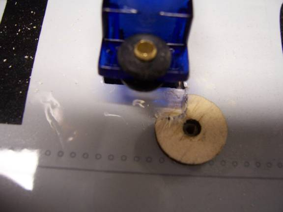
Question: When I am mounting wing servos in the VMAR Bird Dog, the wing strut attachment point washer is in the way of the mounting tab on one of the servos. What do I do? Solution: This is easy to fix. Use a sharp #11 Xacto blade to knotch out the wooden washer as shown in the picture below. Takes about 15 seconds and you'll be good to go. Note that this notching is only required where the strut washer and servo are in contact. This appears only to be an issue on production models up to November 2005.
|
| 1.9.3. VMA-B210X Bird Dog 06-12 ARF - Assembly & Operations Manual in PDF format |
| 1.9.4. VMA-B210X Bird Dog 06-12 ARF - Pictures, Graphics & Artwork |
| 1.9.4.1. Logo VMA-B210X Bird Dog 06-12 ARF |
| 1.9.4.1.1. Logo VMA-B210X Bird Dog 06-12 ARF - JPG (RGB) |
| 1.9.4.1.2. Logo VMA-B210X Bird Dog 06-12 ARF - PSD (PhotoShop) |
| 1.9.4.1.3. Logo VMA-B210X Bird Dog 06-12 ARF - TIF (CMYK) |
| 1.9.4.2. Pictures VMA-B210A Bird Dog 06-12 ARF - Army (Red on White) |
| 1.9.4.2.1. Pictures VMA-B210A Bird Dog 06-12 ARF - Army (Red on White) - JPG (RGB) |
| 1.9.4.2.2. Pictures VMA-B210A Bird Dog 06-12 ARF - Army (Red on White) - PSD (Photoshop) |
| 1.9.4.2.3. Pictures VMA-B210A Bird Dog 06-12 ARF - Army (Red on White) - TIF (CMYK) |
| 1.9.4.3. Pictures VMA-B210U Bird Dog 06-12 ARF - USAF (Yellow on Gray) |
| 1.9.4.3.1. Pictures VMA-B210U Bird Dog 06-12 ARF - USAF (Yellow on Gray) - JPG (RGB) |
| 1.9.4.3.2. Pictures VMA-B210U Bird Dog 06-12 ARF - USAF (Yellow on Gray) - PSD (PhotoShop) |
| 1.9.4.3.3. Pictures VMA-B210U Bird Dog 06-12 ARF - TIF (Yellow on Gray) - PSD (CMYK) |
| 1.9.4.4. Pictures VMA-B210X Bird Dog 06-12 ARF - from the Fan Club |
| 1.9.4.4.1. Pictures - VMA-B210X Bird Dog 06-12 ARF - Courtesy Barry Waters |
| 1.10. VMA-C019 Cap 231EX 90-120 ARF Aerobatic Sport |
| 1.10.1. VMA-C019 Cap 231EX 90-120 ARF Aerobatic Sport - Assembly & Operations Manual in PDF format |
| 1.11. VMA-C0024X Chipmunk 40 Semiscale ARF - Canada & British |
| 1.11.1. VMA-C0024X Chipmunk 40 Semiscale ARF - READ ME FIRST |
| READ ME FIRST - for Models with VCOTE Covering |
The Read Me First for models covered with VCOTE applies to this product and is available at:
The Read Me First will open in a second window. Please review it, print it or email it using the icons located near the top right of the Read Me First page (mouse over each icon for feedback about what it does). When you are finished, close the Read Me First window and continue browing here.
|
| 1.11.2. VMA-C0024X Chipmunk 40 Semiscale ARF - Additional Information |
In general "Additional" Information is:
Subject to the Conditions of Use, please review the attachments and related articles listed below. |
| COPYRIGHT |
Copyright Richmond RC Supply Ltd. All rights reserved.
|
| 1.11.2.1. VMA-C0024X Chipmunk 40 Semiscale ARF - Horizontal Thrust Line |
Question: Where is the horizontal thrust line on the VMAR Chipmunk 40 ARF removeable firewall? |
| 1.11.3. VMA-C0024X Chipmunk 40 Semiscale ARF - Assembly & Operations Manual in PDF format |
| 1.12. VMA-C044 Cap 231EX 40 ARF Aerobatic Sport |
| 1.12.1. VMA-C044 Cap 231EX 40 ARF Aerobatic Sport - READ ME FIRST |
| READ ME FIRST - for Models with POLYCOTE ECS Covering |
The Read Me First for models covered with POLYCOTE ECS applies to this product and is available at:
The Read Me First will open in a second window. Please review it, print it or email it using the icons located near the top right of the Read Me First page (mouse over each icon for feedback about what it does). When you are finished, close the Read Me First window and continue browing here.
|
| 1.12.2. VMA-C044 Cap 231EX 40 ARF Aerobatic Sport - Additional Information |
In general "Additional" Information is:
Subject to the Conditions of Use, please review the attachments and related articles listed below. |
| COPYRIGHT |
Copyright Richmond RC Supply Ltd. All rights reserved.
|
| 1.12.3. VMA-C044 Cap 231EX 40 ARF Aerobatic Sport - Assembly & Operations Manual in PDF format |
| 1.13. VMA-C210X J3 Cub & L4 Grasshopper 09-15 ARF - Elect & Glow - Various Colors |
| 1.13.1. VMA-C210X J3 Cub & L4 Grasshopper 09-15 ARF - READ ME FIRST |
PLEASE READ ME FIRST BEFORE PROCEEDING TO ASSEMBLE OR OPERATE THIS PRODUCT
|
| LIABILITY DISCLAIMER & COPYRIGHT NOTICE |
LIABILITY DISCLAIMER The authors and/or suppliers and/or disseminaters of this information and/or product expressly disclaim any warranties or representations, either expressed or implied, including but not limited to implied warranties of fitness, accuracy, timeliness or applicability of the information and/or product provided here. In no event will the authors and/or suppliers and/or disseminaters of this information and/or product have any obligation arising from contract or tort, for loss of revenue or profit, or for indirect, special, incidental, consequential or other damages of any sort arising from this information and/or product. In using this information and/or product, the user accepts all responsibility for and all liability associated with such use. PROCEEDING WITH THE USE OF THIS INFORMATION AND/OR PRODUCT INDICATES AGREEMENT WITH AND ACCEPTANCE OF THE LIABILITY DISCLAIMER.
|
| Please Note the following Caution |
CAUTION A Remote Control (RC) model aircraft is not a toy. It is a flying model that functions much like a full size airplane. If you do not assemble and operate model aircraft properly you can cause injury to yourself and others and damage property. DO NOT FLY a model aircraft unless you are qualified. You are ultimately responsible for the mechanical, aeronautical and electrical integrity of any model you fly and all of the components that make up the model including but not limited to the airframe itself, control surfaces, hinges, linkages, covering, engine, motor, radio, servos, switches, wiring, battery and parts. Check all components before and after each flight. It is essential that you act with the clear understanding that you are solely responsible for all aspects of the model at all times. DO NOT FLY until it is right.
|
| 1.13.1.1. VMA-C210X J3 Cub & L4 Grasshopper 09-15 ARF - General Information |
|
| COPYRIGHT |
Copyright Richmond RC Supply Ltd. All rights reserved.
|
| Tips for Avoiding Common Problems |
We have supplied thousands and thousands and thousands of model aircraft in the past 20 plus years. We're not bragging! We tell you this to give some credibility to our suggested list of tips that follow. In talking to modelers around the world, here is what we have found is the key to... AVOIDING 90% of PROBLEMS that can arise:
|
| 1.13.1.2. VMA-C210X J3 Cub & L4 Grasshopper 09-15 ARF - Supplement to the Manual |
|
| 1.13.1.2.1. VMA-C210X J3 Cub & L4 Grasshopper 09-15 ARF - Control Horns - Laser Cut Wood |
Question: My VMAR VMA-C210X 09-15 ARF was supplied with control horns that appear to be made of wood. Are these OK? Answer: Yes these are laser cut from aircraft plywood and are strong, light, reliable and easy to install. In some later production J3 Cub and L4 Grasshoppers the horns are laser cut from Mylar sheets. Additional Information: After installing the control horns made from plywood, we recommend wicking thin CA such as Pacer ZAP (Pink) into the plywood of the control horn to "harden" the plywood and holes. Do two applications about 1 minute apart.
|
| 1.13.1.3. VMA-C210X J3 Cub & L4 Grasshopper 09-15 ARF - Important Information |
|
| COPYRIGHT |
Copyright Richmond RC Supply Ltd. All rights reserved.
|
| 1.13.1.3.1. VMA-C210X J3 Cub & L4 Grasshopper 09-15 ARF - Covering |
This model uses POLYCOTE ECS Covering |
| POLYCOTE ECS - Care & Maintenance - Quick Tips |
|
Question: Do you have any pointers regarding the Care & Maintenance of POLYCOTE ECS? Answer: Yes we have this Summary of Quick Tips. See www.richmondrc.com ( Enter Site > Support Services > Knowledge Base then Search on "Covering") for an expanded explanation of each Tip. Polyester offers the best in covering performance and as with any new modern technology, the maintenance methods may be different than those you used with your older covering. This is NOT Monokote or Solarfilm, its different. If you have used ORACOVER or ULTRACOTE you will have some experience with working with POLYESTER as a covering material. Here is our Summary of Quick Tips related to POLYCOTE ECS covering.
|
| 1.13.1.4. Support |
On Line, eMail, Fax, Phone, Mail |
| We offer the Best in Support Services. |
We back up our products and our customers with the best support services available. From our industry leading Knowledge Base to information about your Shipment, we've got you covered!
To access our Support Services please:
Your Choice of Support Services that Work for You:
|
| 1.13.1.4.1. Contact Us |
For Sales and other Inquiries |
| Support - Contact Us - Reach our Sales Department by eMail, Fax, Phone or Mail |
Technical Inquiries: Please review the information provided in our Knowledge Base. After checking our Knowledge Base, if you need further assistance please use our Submit A Question service to get a response within 2 Business Days.
Sales Inquiries: Please note that our Sales Department personnel are trained and dedicated to:
Their depth of technical knowledge is about on par with what is shown in our printed sales literature. In most cases, they are working from the same printed advertisements or content from our web site that you are. Asking sales personnel to confirm the size, color and availability of a product is well within their capabilities. However, asking detailed questions about technical issues is not.
Buy our Products:
For All Other Inquiries... please consult the following resources:
|
| 1.13.1.5. Keep Up to Date |
Check Frequently for Updates |
| Support - Stay Current - Check Frequently for Updated &/or Additional Information |
This information is subject to change without notice. When viewing this information in a printed form the printing date will be visible in the lower right corner. Check frequently for updates &/or Additional Information.at www.richmondrc.com, > Enter the Site, > Support Services, follow the links to our Knowledge Base. Review the Table of Contents and search for the name and/or part number of this product.
For automated notification of changes to information contained in our Knowledge Base please register as a Priority Response member and subscribe to our Priority Response Notification Service.
|
| 1.13.2. VMA-C210X J3 Cub & L4 Grasshopper 09-15 ARF - Additional Information |
In general "Additional" Information is:
Subject to the Conditions of Use, please review the attachments and related articles listed below. |
| COPYRIGHT |
Copyright Richmond RC Supply Ltd. All rights reserved.
|
| 1.13.2.1. VMA-C210X J3 Cub & L4 Grasshopper 09-15 ARF - Quick Release Wing Strut Set #VMA-C210YWSQ |
Question: I travel a great deal and take my VMAR C210X 09-15 ARF with me in my RV. When I'm home, I remove the wing and undo the struts from the fuselage. But when I am travelling I like to remove the struts from the wing as well. I've been undoing the screws and it works OK but I was wondering if you have a strut set that can be removed more easily and quickly for traveling? Answer: Yes we do. For modelers who need to frequently remove the wing struts from the VMAR C210X 09-15 ARF, we have released a new Quick Release Strut Set. For the J3 Cub these struts are Yellow (#VMA-C210YWSQ) and for the L4 Grasshopper these struts are Drab Green (VMA-C210DWSQ). The quick release struts are easier to install and can be removed more quickly that the standard struts. Colored to match the model, the quick release struts use Z-Bend ends for the wing attachment points (2 per strut) instead of using screws and brass plates. Fitting the quick release strut set requires minor modification to the wing attachment points (4). Instructions for modifying the wing attachment points: Caution: be careful with drilling. Don't drill through the wing or your fingers! |
| 1.13.2.2. VMA-C210X J3 Cub & L4 Grasshopper 09-15 ARF - Stage 1 Wing Assembly Joining the Wing Halves - Step 1G Leading Edge Dowel |
Question: Stage 1 of my C210X Manual for the J3 Cub and L4 Grasshopper shows a notch in both wing roots but does not show me when to install the small leading edge dowel. What should I do?
Answer: Your version of the Manual is missing Step 1G and its accompanying picture. After you have completed Step 1F, please do the following:
|
| 1.13.2.3. VMA-C210X J3 Cub & L4 Grasshopper 09-15 ARF - Stage 12 Installing Electric Motor and ESC - Step 12C Mounting Screw (Bolt) Set |
Question: Stage 12 Step 12C of my C210X Manual refers to installing four bolt and washer sets for mounting the motor. These bolt sets are stated to come with the kit but I did not get these in my kit. What's the story here?
Answer: The reference to the bolt sets (mounting screws) in your version of the C210X Manual is incorrect. These mounting screws come with the Power Module and Power Pack but are not included with the kit. Each motor is different and requires different mounting hardware and methods. We do provide a blank firewall set that can be drilled to suit nearly all motors. |
| Mounting Screws - What to use on VMM-111B18VM VMAX Brushless Motor |
Question: I have a VMAX #VMM-111B18VM VMAX Brushless Motor. What do I need in the way of mounting screws? Answer: There are a several options for this depending on what you have in mind:
CAUTION: When mounting motors using any method, ensure all fasteners are tightened securely. Check for vibration free operation of the motor. If not vibration free, reseat and retighten all fasteners and ancilliary components such as props and gears. Tighten fasteners firmly but don't strip the threads. Use medium strength thread locker on all metal to metal fasteners.
|
| 1.13.2.4. VMA-C210X J3 Cub & L4 Grasshopper 09-15 ARF - Stage 12 Installing Electric Motor and ESC - Step 12J Bolt Length |
Question: Stage 12 Step 12J of my C210X Manual for the J3 Cub and L4 Grasshopper refers to installing four bolts for the power module. These bolts are stated to be 50mm long. My bolts are only about 30mm in length. What's the story here?
Answer: The reference to 50mm long bolts in your version of the C210X Manual is incorrect. The bolts are 30 mm long when used in the J3 Cub and L4 Grasshopper. This allows the tapered cowl to be mounted without contacting excess bolt length. The picture and instructions of Step 12K are correct in showing the separation between the fixed fuselage firewall and the nuts to be approximately 22mm. It is this spacing of the nuts and power module firewall at approximately 22mm from the fixed firewall in the fuselage that is important, not the actual length of the bolts themselves. |
| 1.13.2.5. VMA-C210X J3 Cub & L4 Grasshopper 09-15 ARF - Stage 15 Installing The Servos - Step 15B & 15C |
|
|
| 1.13.3. VMA-C210X J3 Cub & L4 Grasshopper 09-15 ARF - Assembly & Operations Manual in PDF format |
| 1.13.4. VMA-C210X J3 Cub & L4 Grasshopper 09-15 ARF - Pictures, Graphics & Artwork |
| 1.13.4.1. Pictures VMA-C210Y J3 Cub 09-15 ARF - Yellow |
| 1.13.4.1.1. Pictures VMA-C210Y J3 Cub 09-15 ARF - Yellow - TIF (CMYK) |
| 1.13.4.2. Pictures VMA-C210D L4 Grasshopper 09-15 ARF - DDay |
| 1.13.4.2.1. Pictures VMA-C210D L4 Grasshopper 09-15 ARF - DDay - TIF (CMYK) |
| 1.13.5. VMA-C210X J3 Cub & L4 Grasshopper 09-15 ARF - Reviews |
| 1.13.5.1. Reviews VMA-C210Y J3 Cub 09-15 ARF - Yellow |
| 1.14. VMA-C260U F4U Corsair 60 SemiScale ECS ARF - US Marines |
| 1.14.1. VMA-C260U F4U Corsair 60 SemiScale ECS ARF - READ ME FIRST |
| READ ME FIRST - for Models with POLYCOTE ECS Covering |
The Read Me First for models covered with POLYCOTE ECS applies to this product and is available at:
The Read Me First will open in a second window. Please review it, print it or email it using the icons located near the top right of the Read Me First page (mouse over each icon for feedback about what it does). When you are finished, close the Read Me First window and continue browing here.
|
| 1.14.2. VMA-C260U F4U Corsair 60 SemiScale ECS ARF - Additional Information |
In general "Additional" Information is:
Subject to the Conditions of Use, please review the attachments and related articles listed below. |
| COPYRIGHT |
Copyright Richmond RC Supply Ltd. All rights reserved.
|
| 1.14.2.1. VMA-C260U F4U Corsair 60 SemiScale ECS ARF - Landing Gear - Retract Ready? |
Question: Is the VMAR Corsair 60 ARF Retract Ready? Answer: No Better Answer: The Corsair comes with fixed gear. It was not designed with retracts in mind and no provision for retracts has been made. It is not retract ready. A great deal of work on the wings and wing structure would be required by modelers if they wish to install retracts in the VMAR Corsair. We have not designed the wing to accept retracts and do not recommend modifying the wing to accept retracts. |
| 1.14.3. VMA-C260U F4U Corsair 60 SemiScale ECS ARF - Assembly & Operations Manual in PDF format |
| 1.14.4. ZBO-Y190611B More Information | ||||||||||||||||||
More Information about #ZBO-Y190611B ... BLOWOUT - VMAR CORSAIR 60 SEMISCALE ARF - FINAL SALE This is a BLOWOUT... FINAL SALE item and the following caution applies:
No other information is available regarding #ZBO-Y190611B BLOWOUT - VMAR CORSAIR 60 SEMISCALE ARF - FINAL SALE. |
| 1.15. VMA-C360X Cessna 182 45-60 Semiscale ARF ECS - Various Colors |
| 1.15.1. VMA-C360X Cessna 182 45-60 Semiscale ARF ECS - READ ME FIRST |
| READ ME FIRST - for Models with POLYCOTE ECS Covering |
The Read Me First for models covered with POLYCOTE ECS applies to this product and is available at:
The Read Me First will open in a second window. Please review it, print it or email it using the icons located near the top right of the Read Me First page (mouse over each icon for feedback about what it does). When you are finished, close the Read Me First window and continue browing here.
|
| 1.15.2. VMA-C360X Cessna 182 45-60 Semiscale ARF ECS - Additional Information |
In general "Additional" Information is:
Subject to the Conditions of Use, please review the attachments and related articles listed below. |
| COPYRIGHT |
Copyright Richmond RC Supply Ltd. All rights reserved.
|
| 1.15.2.1. VMA-C360X Cessna 182 45-60 Semiscale ARF ECS - Extra Parts |
Question: In the shipping box for my VMAR Cessna 182 45-60 ARF ECS I found several extra white plastic parts. What are they for?
Answer: The extra parts are optional but do help to dress up the model. The larger pieces are center wing joint covers. The smaller pieces are fairings that can be slid over the wing struts to hide the end fittings where the struts meet the wing.
|
| 1.15.2.2. VMA-C360X Cessna 182 45-60 Semiscale ARF ECS - Thrust Line Location |
Question: In the instruction manual for the VMAR Cessna 182 45-60 ARF ECS it says to align to the thrust line with the engine "sharp". This is confusing and I don't understand this. What does this mean? Answer: This is a misprint. It is supposed to say "shaft" not "sharp" as in align the thrust line with the engine shaft and specifically refers to the center of the engine shaft. Supplementary Information: Here are some additional articles that may be helpful. |
| Firewall - Thrust Lines - Where are they? Horizontal and Vertical |
Question: I am installing my engine. Where are the thrust lines on the firewall? Answer: The horizontal thrust line normally appears on the forward face of the firewall or you draw the horizontal thrust line on the forward face of the firewall yourself following location instructions contained in the documentation that came with your model. If there is no horizontal line indicated on the firewall and you are unable to locate the location of the line in the reference material there is an easy way to position the horiztonal thrust line youself. To do this, fit your cowl over the fuselage. Look at the cowl from the left and right sides and adjust the vertical angle of the cowl to align with the fuselage. There should not be any sharp drop or rise in the silhouette profile of the fuselage as you move your eye along the fuselage and over the cowl. Once you have the cowl in place, look through the front hole where the crankshaft is going to protrude. Mark the horizontal thrust line on the firewall so that it is evenly located up and down with respect to the hole in the front of the cowl. The vertical thrust line lies up and down through the middle of the firewall. If it is not shown, you can simply draw it into place. Make sure it is in the middle. You may also find this information on our web site. Look for the links to your model, then the link to the detailed information and browse down to the engine section. The position of the horizontal and/or vertical thrust line may be stated there. |
| Engine Orientation - Upright, Sideways, Inverted - Relation to Position on FIrewall |
Question: How do I position my engine on the engine mounts and on the firewall when I intend on installing the engine at an angle or inverted rather than upright? Short Answer: Regardless of orientation, the center line of the crankshaft must be positioned over the intersection of the vertical and horizontal thrust lines for your particular model. There are a few exceptions as described below. Better Answer: Some models pretty much force you to install your engine in an upright orientation. Other models, particularly once you move up from basic trainers, offer you a variety of engine orientation options. Rotated 90 degrees is one such choice that often works well with Pitts style mufflers... inverted (sometimes called 180 degree rotation) is another choice. Generally these non-upright orientations, hide more of the engine and muffler and result in a more realistic scale like appearance to the model. The choice of what angle to use is pretty much up to you, limited by the physical size of the engine, muffler, cowl etc. Some engines for example can be oriented at 90 or 135 degrees but run into a physical problem at other angles... they hit something, the muffler won't clear the fuselage, the needle valve is at an awkward location etc. When selecting an angle to mount your engine, you have to balance off appearance, convenience, practicality and most of all make sure it can physically fit. Don't forget to test your planned installation angle with the muffler and carb installed. Also check out your engine manual for any specific guidance from the engine manufacturer. Some manufacturers don't recommend an exactly inverted 180 degree installation. We have found this to be good advice in many cases... 180 degree inversions have a tendency to smother the glow plug in oil and residue if run at low RPM for too long. Once you've decided on the installation orientation that you want, the actual position of the engine on the firewall is no different with a rotated engine than it is with an upright engine. The engine thrust is always centered around the crankshaft and regardless of orientation, the center line of the crankshaft must be positioned over the intersection of the vertical and horizontal thrust lines for your particular model. The vertical thrust line lies up and down through the middle of the firewall. The horizontal thrust line is often drawn on the firewall or is to be draw on the firewall by you after referencing location information in the model instruction manual. There are some exceptions but the exceptions are few and far between... if the mounting face of the engine mounting lugs is offset from the center line of the crankshaft you have to adjust accordingly. This is rare, we have not seen this in standard two stroke engines. Engine manufacturers avoid this if at all possible. If you are working with a large gas engine adapted from another industry or a multi piston engine, examine the mounting system carefully and make sure you understand the relation between the engine mounting lugs and the center line of the crankshaft.
|
| 1.15.3. VMA-C360X Cessna 182 45-60 Semiscale ARF ECS - Assembly & Operations Manual in PDF format |
| 1.16. VMA-D014 Discovery 40 ARF Hi Wing 63 in. - Various Colors |
| 1.16.1. VMA-D014 Discovery 40 ARF Hi Wing 63 in. - READ ME FIRST |
| READ ME FIRST - for Models with POLYCOTE ECS Covering |
The Read Me First for models covered with POLYCOTE ECS applies to this product and is available at:
The Read Me First will open in a second window. Please review it, print it or email it using the icons located near the top right of the Read Me First page (mouse over each icon for feedback about what it does). When you are finished, close the Read Me First window and continue browing here.
|
| 1.16.2. VMA-D014 Discovery 40 ARF Hi Wing 63 in. - Additional Information |
In general "Additional" Information is:
Subject to the Conditions of Use, please review the attachments and related articles listed below. |
| COPYRIGHT |
Copyright Richmond RC Supply Ltd. All rights reserved.
|
| 1.16.3. VMA-D014 Discovery 40 ARF Hi Wing 63 in. - Assembly & Operations Manual in PDF format |
| 1.17. VMA-D160F Dewoitine D520 45-60 Semiscale ARF ECS - Wood |
| 1.17.1. VMA-D160F Dewoitine D520 45-60 Semiscale ARF ECS - Assembly and Operations Manual |
20200415 |
| 1.17.2. VMA-D160F Dewoitine D520 45-60 Semiscale ARF ECS - Specifications | ||||||||||||||||||||||
|
| 1.18. VMA-D210X DO27 1100 EP 43 in. Electric ARF ECS |
| 1.18.1. VMA-D210X DO27 1100 EP 43 in. Electric ARF ECS - READ ME FIRST |
PLEASE READ ME FIRST BEFORE PROCEEDING TO ASSEMBLE OR OPERATE THIS PRODUCT |
| LIABILITY DISCLAIMER & COPYRIGHT NOTICE |
LIABILITY DISCLAIMER The authors and/or suppliers and/or disseminaters of this information and/or product expressly disclaim any warranties or representations, either expressed or implied, including but not limited to implied warranties of fitness, accuracy, timeliness or applicability of the information and/or product provided here. In no event will the authors and/or suppliers and/or disseminaters of this information and/or product have any obligation arising from contract or tort, for loss of revenue or profit, or for indirect, special, incidental, consequential or other damages of any sort arising from this information and/or product. In using this information and/or product, the user accepts all responsibility for and all liability associated with such use. PROCEEDING WITH THE USE OF THIS INFORMATION AND/OR PRODUCT INDICATES AGREEMENT WITH AND ACCEPTANCE OF THE LIABILITY DISCLAIMER.
|
| Please Note the following Caution |
CAUTION A Remote Control (RC) model aircraft is not a toy. It is a flying model that functions much like a full size airplane. If you do not assemble and operate model aircraft properly you can cause injury to yourself and others and damage property. DO NOT FLY a model aircraft unless you are qualified. You are ultimately responsible for the mechanical, aeronautical and electrical integrity of any model you fly and all of the components that make up the model including but not limited to the airframe itself, control surfaces, hinges, linkages, covering, engine, motor, radio, servos, switches, wiring, battery and parts. Check all components before and after each flight. It is essential that you act with the clear understanding that you are solely responsible for all aspects of the model at all times. DO NOT FLY until it is right.
|
| 1.18.1.1. VMA-D210X DO27 1100 EP 43 in. Electric ARF ECS - General Information |
| COPYRIGHT |
Copyright Richmond RC Supply Ltd. All rights reserved.
|
| Tips for Avoiding Common Problems |
We have supplied thousands and thousands and thousands of model aircraft in the past 20 plus years. We're not bragging! We tell you this to give some credibility to our suggested list of tips that follow. In talking to modelers around the world, here is what we have found is the key to... AVOIDING 90% of PROBLEMS that can arise:
|
| 1.18.1.2. VMA-D210X DO27 1100 EP 43 in. Electric ARF ECS - Supplement to the Manual |
| 1.18.1.2.1. VMA-D210X DO27 1100 EP 43 in. Electric ARF ECS - Electric Power - Options |
Question: I have a VMAR VMA-D210X DO27 1100 EP 43 in. Electric ARF ECS. What do you recommend for a power system?
Answer: We have a couple of options for you to consider:
1) Our VMAX Power Module for the DO27 1100EP is #VMM-D210XPM1. This consists of our VMAX Brushless Motor (#VMC-120B15VC) and our VMAX Electronic Speed Control (ESC) (#VMC-120B15VC). The motor and the ESC have been pre-installed onto the power module firewall to fit your model.
2) Our VMAX Power Pack for the DO27 1100EP (#VMM-D210XPP1) contains the Power Module plus a LiPO battery pack, wiring harness and propeller.
Both of these options have been tested with the VMAR D027 1100EP and help you get into the air quickly and stay there!
|
| 1.18.1.2.2. VMA-D210X DO27 1100 EP 43 in. Electric ARF ECS - Electric Power - Wiring |
Question: How should I wire my VMAR VMA-D210X DO27 1100 EP 43 in. Electric ARF ECS?
Answer: The simplest solution is to use our VMAX Power Pack which comes with a brushless motor, electronic speed control (ESC with BEC), battery pack, propellor etc and includes a custom made wiring harness for the the DO27 1100EP.
The Power Pack for the DO27 11EP IS #VMM-D210XPP1.
If you have purchased the VMAX Power Pack please follow the installation instructions that come with the Power Pack. The VMAX Power Pack will save you hours of time and greatly reduce the chances of making an expensive mistake.
The DO27 1100EP includes a fuse switch assembly that is externally accessible and a short Y-splitter for coupling both aileron servos so that they can be driven from one receiver channel. If you have your own motors, servos, speed controls etc that you intend on using, the manufacturer of these electric components is your best bet for advice.
|
| 1.18.1.3. VMA-D210X DO27 1100 EP 43 in. Electric ARF ECS - Important Information |
|
| COPYRIGHT |
Copyright Richmond RC Supply Ltd. All rights reserved.
|
| 1.18.1.3.1. VMA-D210X DO27 1100 EP 43 in. Electric ARF ECS - Covering |
This model uses POLYCOTE ECS Covering |
| POLYCOTE ECS - Care & Maintenance - Quick Tips |
|
Question: Do you have any pointers regarding the Care & Maintenance of POLYCOTE ECS? Answer: Yes we have this Summary of Quick Tips. See www.richmondrc.com ( Enter Site > Support Services > Knowledge Base then Search on "Covering") for an expanded explanation of each Tip. Polyester offers the best in covering performance and as with any new modern technology, the maintenance methods may be different than those you used with your older covering. This is NOT Monokote or Solarfilm, its different. If you have used ORACOVER or ULTRACOTE you will have some experience with working with POLYESTER as a covering material. Here is our Summary of Quick Tips related to POLYCOTE ECS covering.
|
| 1.18.1.4. Support |
On Line, eMail, Fax, Phone, Mail |
| We offer the Best in Support Services. |
We back up our products and our customers with the best support services available. From our industry leading Knowledge Base to information about your Shipment, we've got you covered!
To access our Support Services please:
Your Choice of Support Services that Work for You:
|
| 1.18.1.4.1. Contact Us |
For Sales and other Inquiries |
| Support - Contact Us - Reach our Sales Department by eMail, Fax, Phone or Mail |
Technical Inquiries: Please review the information provided in our Knowledge Base. After checking our Knowledge Base, if you need further assistance please use our Submit A Question service to get a response within 2 Business Days.
Sales Inquiries: Please note that our Sales Department personnel are trained and dedicated to:
Their depth of technical knowledge is about on par with what is shown in our printed sales literature. In most cases, they are working from the same printed advertisements or content from our web site that you are. Asking sales personnel to confirm the size, color and availability of a product is well within their capabilities. However, asking detailed questions about technical issues is not.
Buy our Products:
For All Other Inquiries... please consult the following resources:
|
| 1.18.1.5. Keep Up to Date |
Check Frequently for Updates |
| Support - Stay Current - Check Frequently for Updated &/or Additional Information |
This information is subject to change without notice. When viewing this information in a printed form the printing date will be visible in the lower right corner. Check frequently for updates &/or Additional Information.at www.richmondrc.com, > Enter the Site, > Support Services, follow the links to our Knowledge Base. Review the Table of Contents and search for the name and/or part number of this product.
For automated notification of changes to information contained in our Knowledge Base please register as a Priority Response member and subscribe to our Priority Response Notification Service.
|
| 1.18.2. VMA-D210X DO27 1100 EP 43 in. Electric ARF ECS - Additional Information |
In general "Additional" Information is:
Subject to the Conditions of Use, please review the attachments and related articles listed below. |
| COPYRIGHT |
Copyright Richmond RC Supply Ltd. All rights reserved.
|
| 1.18.2.1. VMA-D210X DO27 1100 EP 43 in. Electric ARF ECS - Control Rod Length - Adjusting |
Question: Can I adjust the length of the control rods in my model? I want to use my existing servos and shift one servo slightly and when I do that the rods seem slightly too long. What should I do?
Answer: Most VMAR models use an inner and outer plastic rod system for the control rods. At each end, the plastic inner rod usually couples to a threaded metal rod which in turn connects to a clevis.
1) Slightly Longer Control Rods: You can make the control rods slightly longer by adjusting the position of the clevis on the threaded metal rod at each end. Do not over do it or the clevis could come off under load. Tug test to ensure you have a secure coupling after any adjustment. 2) Much Longer Control Rods: You will need to change either the metal threaded rods at each end (we have these in stock in various lengths) OR cut the inner plastic rod and splice an additional piece of the splined plastic rod into place. Use 2mm threaded metal studs as couplers. Tug test to ensure you have a secure coupling after any such modification. 3) Shorter Control Rods: You can make the control rods slightly shorter by adjusting the position of the clevis on the threaded metal rod at each end. Tug test to ensure you have a secure coupling after any adjustment. To further reduce the control rod length:
4) If in any doubt about the security of any coupling, unthread the clevis and wick thin CA into the coupling between the stud and the plastic tube. Do not get CA into the clevis threads. |
| 1.18.2.2. VMA-D210X DO27 1100 EP 43 in. Electric ARF ECS - Extra Hardware Items |
Question: I have completed the assembly of my VMAR VMA-D210X DO27 1100 EP 43 in. Electric ARF ECS and I have a few extra hardware items such as horns, screws and wing bolts. What are these for?
Answer: We usually include a few extra horns and wing bolts with all VMAR ARF's. You may also find a spare clevis and a couple of small screws depending on the model. These are free and intended to help you out if you drop or misplace one of these small items. If you have followed all of the assembly steps, completed your model, tested that your radio and control surfaces all move correctly, tug tested everything twice, just put any of extra hardware pieces in one of the bags and set it aside as spares just in case you need them later on. Don't throw anything out, you just never know when that screw, horn or nut may be needed!
|
| 1.18.2.3. VMA-D210X DO27 1100 EP 43 in. Electric ARF ECS - Glow Power - Tips |
|
Question: Can I use a glow engine to power my VMAR VMA-D210X DO27 1100 EP 43 in. Electric ARF ECS. If so what sizes are recommended? Any tips you can suggest on what I need to plan for?
Answer: Yes the VMAR VMA-D210X DO27 1100 EP 43 in. Electric ARF ECS can be powered with a glow engine. We suggest glow engines be .06 to .10 cu. in.Please note that this model has been intended for Electric Flight and does not come with a tank or engine mount. It does however utilize the VMAR power module system which makes it easier to modify the propulsion system to glow.
Tips on use of glow power: 1) We recommend two stroke engines for this model. Four stroke engines tend to be bigger and heavier.
2) You will need to plan your fuel tank and engine mounting system with careful consideration for physical space particularly if you wish to try to install the engine so that you can use the cowl
3) Use Pacer Finishing Resin and a brush to throughly seal any exposed wood, particularly that of the firewall, the power module forward firewall and the attachment area on the wing. Also the wing saddle area. The exhaust from glow engines contains lots of hot vapourized and liquid oil residue. Although most of this oil will be channeled out in the exhaust, some oil will inevitably get on the model itself and will be absorbed by any unsealed wood. Oil can weaken glue joints and the wood itself.
4) Glow engines tend to produce considerable vibration particularly if the propellor is not balanced correctly. Take particular care to balance your propellor. Vibration can cause fuel feed problems, lean runs and engine cut off as well as structural failure, control surface flutter and/or separation and is very damaging to servos. It is very important to keep vibration to a minimum.
|
| 1.18.2.4. VMA-D210X DO27 1100 EP 43 in. Electric ARF ECS - Stage 11 Installing Electric Motor and ESC - Step 11C Mounting Screw (Bolt) Set |
Question: Stage 11 Step 11C of my D210X Manual refers to installing four bolt and washer sets for mounting the motor. These bolt sets are stated to come with the kit but I did not get these in my kit. What's the story here?
Answer: The reference to the bolt sets (mounting screws) in your version of the D210X Manual is incorrect. These mounting screws come with the Power Module and Power Pack but are not included with the kit. Each motor is different and requires different mounting hardware and methods. We do provide a blank firewall set that can be drilled to suit nearly all motors. |
| Mounting Screws - What to use on VMM-111B18VM VMAX Brushless Motor |
Question: I have a VMAX #VMM-111B18VM VMAX Brushless Motor. What do I need in the way of mounting screws? Answer: There are a several options for this depending on what you have in mind:
CAUTION: When mounting motors using any method, ensure all fasteners are tightened securely. Check for vibration free operation of the motor. If not vibration free, reseat and retighten all fasteners and ancilliary components such as props and gears. Tighten fasteners firmly but don't strip the threads. Use medium strength thread locker on all metal to metal fasteners.
|
| 1.18.3. VMA-D210X DO27 1100 EP 43 in. Electric ARF ECS - Assembly & Operations Manual in PDF format |
| 1.18.4. VMA-D210X DO27 1100 EP 43 in. Electric ARF ECS - Specifications | ||||||||||||||||||||||
|
| 1.19. VMA-D260X Dornier DO27 45-61 ARF ECS - Various Colors |
| 1.19.1. VMA-D260X Dornier DO27 45-61 ARF ECS - READ ME FIRST |
PLEASE READ ME FIRST BEFORE PROCEEDING TO ASSEMBLE OR OPERATE THIS PRODUCT
|
| LIABILITY DISCLAIMER & COPYRIGHT NOTICE |
LIABILITY DISCLAIMER The authors and/or suppliers and/or disseminaters of this information and/or product expressly disclaim any warranties or representations, either expressed or implied, including but not limited to implied warranties of fitness, accuracy, timeliness or applicability of the information and/or product provided here. In no event will the authors and/or suppliers and/or disseminaters of this information and/or product have any obligation arising from contract or tort, for loss of revenue or profit, or for indirect, special, incidental, consequential or other damages of any sort arising from this information and/or product. In using this information and/or product, the user accepts all responsibility for and all liability associated with such use. PROCEEDING WITH THE USE OF THIS INFORMATION AND/OR PRODUCT INDICATES AGREEMENT WITH AND ACCEPTANCE OF THE LIABILITY DISCLAIMER.
|
| Please Note the following Caution |
CAUTION A Remote Control (RC) model aircraft is not a toy. It is a flying model that functions much like a full size airplane. If you do not assemble and operate model aircraft properly you can cause injury to yourself and others and damage property. DO NOT FLY a model aircraft unless you are qualified. You are ultimately responsible for the mechanical, aeronautical and electrical integrity of any model you fly and all of the components that make up the model including but not limited to the airframe itself, control surfaces, hinges, linkages, covering, engine, motor, radio, servos, switches, wiring, battery and parts. Check all components before and after each flight. It is essential that you act with the clear understanding that you are solely responsible for all aspects of the model at all times. DO NOT FLY until it is right.
|
| 1.19.1.1. VMA-D260X Dornier DO27 45-61 ARF ECS - General Information |
|
| COPYRIGHT |
Copyright Richmond RC Supply Ltd. All rights reserved.
|
| Tips for Avoiding Common Problems |
We have supplied thousands and thousands and thousands of model aircraft in the past 20 plus years. We're not bragging! We tell you this to give some credibility to our suggested list of tips that follow. In talking to modelers around the world, here is what we have found is the key to... AVOIDING 90% of PROBLEMS that can arise:
|
| 1.19.1.2. VMA-D260X Dornier DO27 45-61 ARF ECS - Supplement to the Manual |
| COPYRIGHT |
Copyright Richmond RC Supply Ltd. All rights reserved.
|
| 1.19.1.2.1. VMA-D260X Dornier DO27 45-61 ARF ECS - Ailerons and Flaps - Locations |
This supplementary information applies to manuals with a copyright date of 20030321 (see back cover). Manuals having later copyright dates may already reflect this supplementary information. Please note that this model has ailerons located outboard on the wings and flaps located inboard on the wings. The ailerons are activated by a servo in the bottom of each wing. The flaps are optional and will require two servos located in the more inboard wing cavities. |
| 1.19.1.2.2. VMA-D260X Dornier DO27 45-61 ARF ECS - Control Horns |
|
| Control Horn Installation - How to |
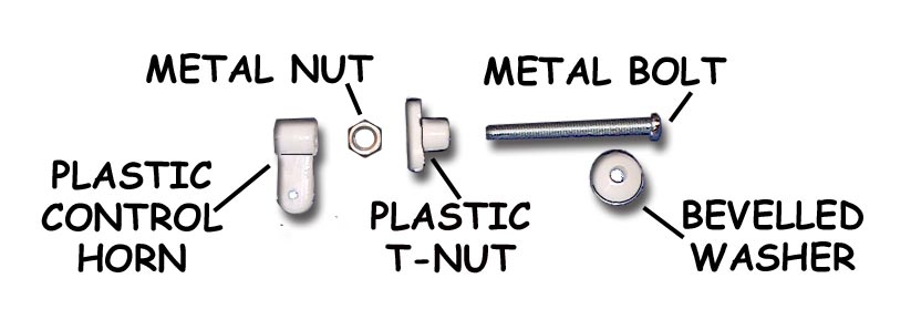
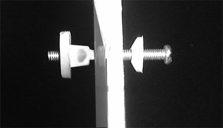
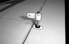
Question: How are VMAR control horns installed? The iillustration below and to the left shows a control horn set before installation. Note 5 parts make up the set. In Light Duty applications the Metal Nut may not be included and only 4 parts will make up the set. The illustration below and to the right shows a control horn set partially installed. Although illustrations in various manuals show the bevelled washer with the bevel pointing away from the surface we find that we get a cleaner strong installation with the bevel pointing inwards. We recommend wicking thin CA such as Pacer ZAP/CA (Pink) into the exposed wood surrounding the hole in the control surface. This helps further strengthen the wood. This is not a requirement but if you are pushing the power limits or planning on extreme aerobatics or speeds, the extra strength could come in handy. Use two applications of thin CA 1 minute apart, BEFORE installing the control horn.
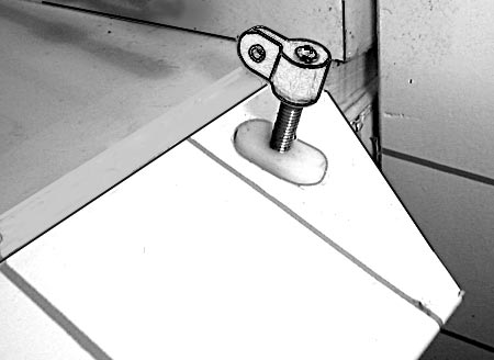
The illustration below shows horn side view of a control horn set fully installed. The illustration to the left is a lighter duty application without the metal nut. The illustration to the right shows a heavier duty application with the metal nut installed. If the metal nuts have been supplied with the horns, we recommend using them.
|
| 1.19.1.2.3. VMA-D260X Dornier DO27 45-61 ARF ECS - Cowl - Handle Carefully |
This supplementary information applies to manuals with a copyright date of 20030321 (see back cover). Manuals having later copyright dates may already reflect this supplementary information. Please handle the cowl carefully. The cowl has been pre-painted to match the appearance of the full size aircraft that this model has been based upon. The shape of the cowl will be most realistic when fitted over the firewall.
|
| 1.19.1.2.4. VMA-D260X Dornier DO27 45-61 ARF ECS - Engine & Prop Size - Recommendations |
This supplementary information applies to manuals with a copyright date of 20030321 (see back cover). Manuals having later copyright dates may already reflect this supplementary information. This model flies well on a .46 size two stroke engine such as the VMAX 46PRO or a .52 size two stroke engine such as the VMAX 52PRO. We suggest using a larger diameter lower pitch prop that you might have used on another model with a similar sized engine. Check your engine manual and select a prop that is at the maximum diameter in the recommended range of props for your engine. We have found that a .46 works well on this model with an 11 x 5 or 12 x 4 prop. The idea here is to locate the thrust out beyond the edge of the fuselage and cowl. A larger diameter prop helps accomplish this.
|
| 1.19.1.2.5. VMA-D260X Dornier DO27 45-61 ARF ECS - Fuel Tank Installation - Page 9 & 10, Stage 18 |
This supplementary information applies to manuals with a copyright date of 20030321 (see back cover). Manuals having later copyright dates may already reflect this supplementary information. Please see Page 4, Stage 5, Figures 5.1 and 5.2 Some servos have a rubber boot strain relief around the wire coming from the servo. Notch the bottom of the servo rails shown in Figures 5.1 and 5.2 to clear the rubber root or wire if required.
|
| 1.19.1.2.6. VMA-D260X Dornier DO27 45-61 ARF ECS - Long Servo Arm - Page 4 & 5, Stage 5 & 6 |
This supplementary information applies to manuals with a copyright date of 20030321 (see back cover). Manuals having later copyright dates may already reflect this supplementary information. Please see Page 4 & 5, Stage 5 & 6,
Use a long servo arm and mount the servo as close to the servo cover plate as possible to maximize the length of the servo arm protruding from the bottom of the wing.
|
| 1.19.1.2.7. VMA-D260X Dornier DO27 45-61 ARF ECS - Servo Boot Clearance - Page 4, Stage 5, Figure 5.1 & 5.2 |
This supplementary information applies to manuals with a copyright date of 20030321 (see back cover). Manuals having later copyright dates may already reflect this supplementary information. Please see Page 4, Stage 5, Figures 5.1 and 5.2 Some servos have a rubber boot strain relief around the wire coming from the servo. Notch the bottom of the servo rails shown in Figures 5.1 and 5.2 to clear the rubber root or wire if required.
|
| 1.19.1.2.8. VMA-D260X Dornier DO27 45-61 ARF ECS - Servo Cover Plates - Aileron & Flaps - Page 4 & 5, Stage 5 & 6 |
This supplementary information applies to manuals with a copyright date of 20030321 (see back cover). Manuals having later copyright dates may already reflect this supplementary information. Please see Page 4, Stage 5, Figures 5.1 and 5.2 Some servos have a rubber boot strain relief around the wire coming from the servo. Notch the bottom of the servo rails shown in Figures 5.1 and 5.2 to clear the rubber root or wire if required.
|
| 1.19.1.2.9. VMA-D260X Dornier DO27 45-61 ARF ECS - Trim Pieces - Test before Cleaning |
This supplementary information applies to manuals with a copyright date of 20030321 (see back cover). Manuals having later copyright dates may already reflect this supplementary information. The factory has supplied a number of trim pieces. Many of these pieces such as the chin blocks on either side of the fuselage near the cowl and the spats on the main landing gear legs have been pre-applied and painted with epoxy paint. Always test these painted surfaces for compatibitliy with any fuels, solvents or cleaning solutions. Review and follow our recommendations regarding cleaning your model.
|
| 1.19.1.3. VMA-D260X Dornier DO27 45-61 ARF ECS - Important Information |
|
| COPYRIGHT |
Copyright Richmond RC Supply Ltd. All rights reserved.
|
| 1.19.1.3.1. VMA-D260X Dornier DO27 45-61 ARF ECS - Covering |
This model uses POLYCOTE ECS Covering |
| POLYCOTE ECS - Care & Maintenance - Quick Tips |
|
Question: Do you have any pointers regarding the Care & Maintenance of POLYCOTE ECS? Answer: Yes we have this Summary of Quick Tips. See www.richmondrc.com ( Enter Site > Support Services > Knowledge Base then Search on "Covering") for an expanded explanation of each Tip. Polyester offers the best in covering performance and as with any new modern technology, the maintenance methods may be different than those you used with your older covering. This is NOT Monokote or Solarfilm, its different. If you have used ORACOVER or ULTRACOTE you will have some experience with working with POLYESTER as a covering material. Here is our Summary of Quick Tips related to POLYCOTE ECS covering.
|
| 1.19.1.4. Support |
On Line, eMail, Fax, Phone, Mail |
| We offer the Best in Support Services. |
We back up our products and our customers with the best support services available. From our industry leading Knowledge Base to information about your Shipment, we've got you covered!
To access our Support Services please:
Your Choice of Support Services that Work for You:
|
| 1.19.1.4.1. Contact Us |
For Sales and other Inquiries |
| Support - Contact Us - Reach our Sales Department by eMail, Fax, Phone or Mail |
Technical Inquiries: Please review the information provided in our Knowledge Base. After checking our Knowledge Base, if you need further assistance please use our Submit A Question service to get a response within 2 Business Days.
Sales Inquiries: Please note that our Sales Department personnel are trained and dedicated to:
Their depth of technical knowledge is about on par with what is shown in our printed sales literature. In most cases, they are working from the same printed advertisements or content from our web site that you are. Asking sales personnel to confirm the size, color and availability of a product is well within their capabilities. However, asking detailed questions about technical issues is not.
Buy our Products:
For All Other Inquiries... please consult the following resources:
|
| 1.19.1.5. Keep Up to Date |
Check Frequently for Updates |
| Support - Stay Current - Check Frequently for Updated &/or Additional Information |
This information is subject to change without notice. When viewing this information in a printed form the printing date will be visible in the lower right corner. Check frequently for updates &/or Additional Information.at www.richmondrc.com, > Enter the Site, > Support Services, follow the links to our Knowledge Base. Review the Table of Contents and search for the name and/or part number of this product.
For automated notification of changes to information contained in our Knowledge Base please register as a Priority Response member and subscribe to our Priority Response Notification Service.
|
| 1.19.2. VMA-D260X Dornier DO27 45-61 ARF ECS - Assembly & Operations Manual in PDF format |
| 1.19.3. VMA-D260X Dornier DO27 45-61 ARF ECS - Pictures, Graphics & Artwork |
| 1.19.3.1. Logo VMA-D260X Dornier DO27 45-61 ARF ECS |
| 1.19.3.1.1. Logo (CMYK_TIF) VMA-D260X Dornier DO27 45-61 ARF ECS |
| 1.19.3.2. Pictures VMA-D260D Dornier DO27 45-61 ARF ECS - Military |
| 1.19.3.2.1. Pictures (CMYK_TIF) VMA-D260D Dornier DO27 45-61 ARF ECS - Military |
| 1.19.3.3. Pictures VMA-D260Z Dornier DO27 45-61 ARF ECS - Civilian |
| 1.19.3.3.1. Pictures (CMYK_TIF) VMA-D260D Dornier DO27 45-61 ARF ECS - Civilian |
| 1.20. VMA-D290Z Dornier DO27 120+ Semiscale ARF |
| 1.20.1. VMA-D290Z Dornier DO27 120+ Semiscale ARF - Assembly & Operations Manual in PDF format |
| 1.21. VMA-D310X DO335 1240/300 Twin EP ARF ECS Electric - Various Colors |
Technical Information related to the VMAR DO335 1240/300 Twin EP ARF ECS Electric
|
| 1.21.1. VMA-D310X DO335 1240/300 Twin EP ARF ECS Electric - Assembly & Operations Manual in PDF format |
| 1.21.2. VMA-D310X DO335 1240/300 Twin EP ARF ECS Electric - Specifications | ||||||||||||||||||
|
| 1.22. VMA-E0014 Extra 300L 40-46 ARF ECS Sport |
| 1.22.1. VMA-E0014 Extra 300L 40-46 ARF - Read Me First |
Please see guidance attached.pdf. |
| 1.22.2. VMA-E0014 Extra 300L 40-46 ARF - Parts, Options and Accessories |
| 1.22.3. ZBO-Y190605A More Information | ||||||||||||||||||
More Information about #ZBO-Y190605A ... BLOWOUT - VMAR EXTRA 300L 40 ARF - FINAL SALE This is a BLOWOUT... FINAL SALE item and the following caution applies:
No other information is available regarding #ZBO-Y190605A BLOWOUT - VMAR EXTRA 300L 40 ARF - FINAL SALE. |
| 1.23. VMA-ETS120 Model Engine Test Stand |
| 1.23.1. Firewalls Not Tight on VMA-ETS120 Model Engine Test Stand |
We have received a some feedback re the firewalls on the VMAR Model Engine Test Stand being loose. This is a hazardous situation and users are cautioned to ensure that the Firewalls are not loose and do not become loose during operation. Resolution: In Brief: Review the safety instructions in the instruction book. Wear eye protection and stay well clear of the propellor and ahead of the propeller. See Page 10 Section 3.2.2 of the instruction book and note the importance of keeping the firewalls fitting SNUGLY between the steel beams. Tighten the bolts, apply the extra locking nuts to each bolt and check bolt and firewall tightness frequently. Reduce vibration. In Detail: Firstly review the safety instructions. Wear eye protection and stay well clear of the propellor and ahead of the propeller. The cinch bolts should be firmly tightened during assembly and the extra locking nuts should be applied to help keep the bolts from backing off under vibration. Everything possible should be done to reduce vibration when running an engine in the test stand... balance the propellor and the spinner... tighten the engine hold down clamps and engine mount bolts and firmly screw or clamp the entire Model Engine Test Stand to a heavy bench or other suitable surface before operating. Check and watch for any loosening of the cinch bolts, locking nuts, engine clamps, firewalls or other fasteners. Stop the engine if anything appears to be loosening up or appears visually blurry when you are looking at it. Do NOT operate the engine test stand unattended!
|
| 1.23.2. VMA-ETS120 Model Engine Test Stand - Rust on Metal Parts |
Question: I have bought a VMAR Engine Test Stand #VMA-ETS120. Some of the metal hardware appears to be rusty. Is this a problem? What should I do?
Answer: This item is sourced from a factory in Southeast Asia. The temperature and humidity in the tropics are both high and the combination of high temperature and high humidity creates surface rust on all ferrous materials even when they are treated with normal plating.
The rust is surface based only and does not affect the utility or longevity of the product. Remember that an engine test stand will normally be literally dripping with oil within a few minutes of first use.
If you wish to remove the rust, one simple trick is to put the metal parts in a sock or bag and wash them with dishwasher soap in a dishwasher. Do NOT use the dry cycle... wash only. Then remove the metal parts and dry them by hand using a paper towel. Any rust remaining on rods or flat metal plates can then be removed using a bit of sandpaper. Finally, use a few drops of WD40 or 3-in-1 Oil to lubricate the bolt threads and you will be good to go.
|
| 1.24. VMA-E160X Edge 540T 45-61 ARF ECS Sport |
|
| 1.24.1. Parts Check Off List - Does not match Box contents |
Question: I have a VMAR Edge 540T and I notice that the parts check off list for some of the minor hardware does not match what I received in the kit. What is going on? Answer: The parts in the Edge 540T are correct but the checkoff list is wrong. Better Answer: We fouled up when printing the instruction book. The instruction book is correct in and of itself but the component check off list was copied from a model without plug in wings. The Edge 540T has plug in wings and therefore some of the parts like the wing joiner, dowels etc are not required on this model and are not included. |
| 1.24.2. Plastic Wing Root Pieces - To seal between the Fuselage and Wing Roots |
Question: I found two plastic pieces that appear to match the shape of the wing roots. What are these for? Answer: These are a bonus component that was added to this model. Usually they appear on one "sheet" of plastic and can be cut out and mounted by the modeler after assembly. These are wing root fairings or covers and serve to provide a cleaner seal between the wing roots and the sides of the fuselage. They can be cut a bit large initially and then trimmed to fit. Supplementary Information: Are they absolutely necessary? No they are not. They provide a better seal and look nice but they are not mandatory for flight. What adhesive should I use to mount these? Always test any adhesive on a small out of view area of any painted or plastic component before proceeding. We generally recommend Pacer Dap-A-Goo for this type of component in this type of application. Dap-A-Goo is a silicone like material that has a solvent base rather than acetic acid and it dries quickly, fuel proof, relatively clear and best of all it sticks to just about any plastic and stays slightly flexible. Remember... ALWAYS TEST FIRST! |
| 1.25. VMA-E24XX Easy 3D ARF ECS - Various Colors |
| 1.25.1. VMA-E24XX Easy 3D ARF ECS - Additional Information |
In general "Additional" Information is:
Subject to the Conditions of Use, please review the attachments and related articles listed below. |
| COPYRIGHT |
Copyright Richmond RC Supply Ltd. All rights reserved.
|
| 1.25.1.1. VMA-E240X Easy 3D 40-52 & Electric ARF - Aileron Horn Hole Location |
Question: We have a VMAR Easy 3D and find that when we install the aileron servos and the aileron control horns they don't quite line up and the control rod ends up not quite perpendicular to the hinge line. Can we move the control horn slightly?
Answer: Yes. Simply redrill the control horn bolt holes so that your aileron control horn aligns better with your aileron servo arm. Depending on your servo arm length and the orientation of your servo you may wish to redrill the new horn bolt hole slightly inboard or slightly outboard of its original location.
To fill in the original hole use Epoxy or a short length of wood dowel.
|
| 1.25.2. VMA-E24XX Easy 3D ARF ECS - Assembly & Operations Manual |
| 20190602... the manufacturer (VMAR) has supplied a manual for the 45-52 Glow Powered version of this model. The manual for the glow powered model provided with the Glow powered model and with the Electric powered version to serve as a guide to the assembly process. |
| 1.25.3. VMA-E24XX Easy 3D ARF ECS - Specifications | ||||||||||||||||||||||||||||
|
| COPYRIGHT |
Copyright Richmond RC Supply Ltd. All rights reserved.
|
| 1.25.4. VMA-E24EX Easy 3D ARF ECS - Using Glow Power |
Question: Is the VMAR Easy 3D intended for electric or glow power? I would like to use glow power. Can this be done?
Answer: Although some Easy 3D's are produced with the assumption that glow power will be used, most are produced with electric power in mind. The airframe is the same in any event. Only the power systems vary.
To use glow power in an Easy 3D that was intended for electric power (i.e. it was not shipped with a fuel tank or glow power engine mount) please see the sub-article below to configure your Easy 3D for glow power using our Glow Engine Installation Pack (#VMA-E240EIP) for the Easy 3D that includes a set of templates and the parts you require. The templates will also be helpful to modelers who are "going it alone" without our Installation Pack.
|
| 1.25.4.1. VMA-E240EIP Glow Engine Installation Pack for VMAR Easy 3D 45-52 ARF - READ ME FIRST |
PLEASE READ ME FIRST BEFORE PROCEEDING TO ASSEMBLE OR OPERATE THIS PRODUCT
|
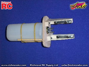
| LIABILITY DISCLAIMER & COPYRIGHT NOTICE |
LIABILITY DISCLAIMER The authors and/or suppliers and/or disseminaters of this information and/or product expressly disclaim any warranties or representations, either expressed or implied, including but not limited to implied warranties of fitness, accuracy, timeliness or applicability of the information and/or product provided here. In no event will the authors and/or suppliers and/or disseminaters of this information and/or product have any obligation arising from contract or tort, for loss of revenue or profit, or for indirect, special, incidental, consequential or other damages of any sort arising from this information and/or product. In using this information and/or product, the user accepts all responsibility for and all liability associated with such use. PROCEEDING WITH THE USE OF THIS INFORMATION AND/OR PRODUCT INDICATES AGREEMENT WITH AND ACCEPTANCE OF THE LIABILITY DISCLAIMER.
|
| Please Note the following Caution |
CAUTION A Remote Control (RC) model aircraft is not a toy. It is a flying model that functions much like a full size airplane. If you do not assemble and operate model aircraft properly you can cause injury to yourself and others and damage property. DO NOT FLY a model aircraft unless you are qualified. You are ultimately responsible for the mechanical, aeronautical and electrical integrity of any model you fly and all of the components that make up the model including but not limited to the airframe itself, control surfaces, hinges, linkages, covering, engine, motor, radio, servos, switches, wiring, battery and parts. Check all components before and after each flight. It is essential that you act with the clear understanding that you are solely responsible for all aspects of the model at all times. DO NOT FLY until it is right.
|
| 1.25.4.1.1. VMA-E240EIP Glow Engine Installation Pack for VMAR Easy 3D 45-52 ARF - General Information |
|
| COPYRIGHT |
Copyright Richmond RC Supply Ltd. All rights reserved.
|
| Tips for Avoiding Common Problems |
We have supplied thousands and thousands and thousands of model aircraft in the past 20 plus years. We're not bragging! We tell you this to give some credibility to our suggested list of tips that follow. In talking to modelers around the world, here is what we have found is the key to... AVOIDING 90% of PROBLEMS that can arise:
|
| 1.25.4.1.2. VMA-E240EIP Glow Engine Installation Pack for VMAR Easy 3D 45-52 ARF - Important Information |
When mounting your throttle servo you will need to install two mounting rails or a servo tray for the throttle servo. The Glow Engine Installation Pack does not include the rails or servo tray for the throttle servo. |
| COPYRIGHT |
Copyright Richmond RC Supply Ltd. All rights reserved.
|
| 1.25.4.1.3. VMA-E240X Easy 3D 45-52 ARF - Preparing for Glow Power - Templates |
To prepare your Easy 3D for glow power, please review the Easy 3D Assembly and Operations Manual. Note in particular Step 14 Fitting the Fuel Tank and Step 15 Installing the Engine. Pictures 14D and 15A illustrate the engine mount, and power module firewall mounted at a 207 degree angle that works well for the VMAX 46PRO and VMAX 52PRO engines and other engines that have an beam mount spacing of approximately 1.53 in. (65 mm). (This is equivalent to a distance of 2.56 in. (65mm) between the outside faces of the beam mounts when clamped to the motor.)
In addition to an engine such as the VMAX 46PRO or 52PRO or similar two stroke engine you will require a fuel tank, two 7/32" diameter wooden dowels about 3.5 inches long, an engine mount (set of T-beams) and a piece of 3/16" plywood for the firewall. If you purchased the glow engine version of the Easy 3D you will find these parts included with your Easy 3D. If they were not included with your Easy 3D you will need to obtain these items either separately or as a set in our Glow Engine Installation Pack for the Easy 3D.
For reference, the individual parts are as follows (included in the Glow Engine Installation Pack #VMA-E240XEIP):
You also will require Pacer ZAP-A-GAP CA+, a Glue Stick such as Super Glue Corp #SGC-GS88 and Pacer Dap-A-Goo or Silicone Sealer such as Super Glue Corp #SGC-THC. You may also require Pacer Finishing Resin and Pacer 30 Minute Epoxy. We have prepared a set of templates to assist you with shaping the plywood firewall, installing the engine mount and modifying the fixed firewall at the front of the fuselage. These Templates are printed on sheets for cutout with scissors and are included with the Glow Engine Installation Pack for the Easy 3D. The Templates also can be downloaded from the attached file links below.
Please note that the Super Glue Corp Glue Stick #SGC-GS88 we have recommended contains a water soluble adhesive that is used to hold the templates into place. Once the work has been completed the templates can be peeled off and the adhesive removed from the wood surfaces using a moist cloth leaving a clean residue free surface.
For tools to make the job easier we suggest a fine toothed scroll saw, Dremel tool with drum sander, sandpaper, a drill or drill press and a set of drill bits.
|
| 1.25.4.1.4. VMA-E240X Easy 3D 45-52 ARF - Make the Power Module Firewall | ||||
Please review Pictures 14D and 15A in the Easy 3D Assembly and Operations Manual. The power module firewall is the plywood piece that the engine "T-beam" mounts are attached to. The fuel tank is attached to the power module firewall and the fuel tank stopper and in/out tubes extend from the tank forward and through the power module firewall.
Use Template A. Use scissors to trim to the outer perimeter of the power module firewall as shown on Template A. Attach the template to a suitably sized piece of good quality 3/16 inch plywood using a glue stick. You may wish to only attach the center and perimeter of the template to the firewall if you wish to more easily remove the template from your firewall later on.
Center punch the two holes marked A and the center hole at the intersection pont of all of the lines. Drill all three center punch locations with a 7/32" drill.
Use a scroll saw to cut the plywood to match the perimeter shape of the template.
|
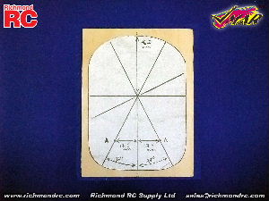
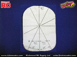
| 1.25.4.1.5. VMA-E240X Easy 3D 45-52 ARF - Align the Engine Mount (T-beams) | ||||||
After completing the cutting and drilling of your power module firewall, review Pictures 14D and 15A in the Easy 3D Assembly and Operations Manual.
Use Template B. This template is used to position the T-beam engine mounts and subsequently drill the T-beam mounting holes in the power module firewall. This template is for the VMAX 46PRO, 52PRO and similar engines that mount on T-beams with approximately 1.53 in spacing (38mm) between the lug portion of the beams. If your engine mounting lugs require T-beam spacing that cannot work with 38mm spacing you can modify the template by cutting the template vertically along the center line and increasing or decreasing the distance between the resultant template halves to reflect the size of your engine.
The Template B sheet contains a expanded depiction of a typical T-beam mount and engine installation. Use scissors to cut out just the retangle bounded by the T-beam mounts as shown in Template B. Consult the pictures before cutting. You want to end up with Template B looking like the lighter (whiter) shaded paper shown in the pictures below.
Position the center point of Template B over the center line intersection point of Template A on the power module firewall. Rotate Template B 207 degrees counter clockwise from horizontal until the engine lug lines on Template B align with the corresponding diagonal lines (Z1 to Z1 and Z2 to Z2) shown on Template A attached earlier to the firewall. Ensure the center point of Template B remains centered over the fuel tank outlet hole while the lug line remains aligned diagonally. Secure Template B in this position using adhesive from a glue stick.
Use a scroll saw to cut the fuel tank outlet clearance hole in the plywood as shown on the template.
Center punch the four holes marked B. Drill all three center punch locations with a 5/32 inch drill. You can use a 3/16" drill if you wish to provide a bit looser tolerance. After drilling the holes, turn the firewall over and counter sink these four holes from the back of the wirewall using a 27/64 in. drill. Counter sink the holes to a depth of the thickness of a washer (approx 1-1.5mm) at the perimeter of the counter sunk holes.
If you wish to seal the power module firewall, now is the time to do it. This is not mandatory but makes for a neater more professional looking finish. Remove the templates and wipe away any adhesive residue. Blow off any dust. Coat all surfaces with Pacer Finishing Resin. Set aside to cure.
|
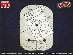
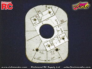
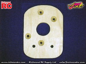
| 1.25.4.1.6. VMA-E240X Easy 3D 45-52 ARF - Install the Engine Mount (T-beams) | ||||
After aligning the engine mount T-beam mounting holes, you are ready to install the engine mounts.
Use four hex head 4mm bolts with washers under the heads. Insert the bolts through the firewall from the backside of the firewall. Position the T-beam mounts as shown in Pictures 14D and 15A in the Assembly and Operations Manual.
Loosely screw all four bolts through the firewall and though the T-beams and into 4 mm nuts before tightening any one bolt or nut. Once all bolts are inserted through firewall and the T-beams and engaged with the 4mm nuts, tighten the bolts and nuts snugly. Ensure the washers on the back side of the firewall sink down into the counter sink holes so that the outer surface of the washers are flush with the back surface of the power module firewall. Wait for 1 hour and then apply Pacer Z42 Blue Threadlocker to the nuts and the threads near the nuts. Retighten the bolts snugly.
|
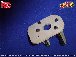
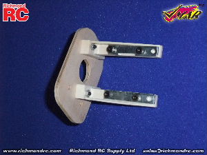
| 1.25.4.1.7. VMA-E240X Easy 3D 45-52 ARF - Install the Fuel Tank | ||||
After installing the engine mount T-beams and securing the nuts and bolts please review Step 14 in the Assembly and Operations Manual. Prepare your fuel tank per Step 14 and the associated pictures.
From the back of the firewall, insert the two 7/32 x 3.5 inch dowels into the 7/32 dowel holes drilled using Template A. If you are using 1/4 in. dowels, redrill the holes to 1/4" inside diameter. Insert the dowels only to the point where their forward ends are flush with the forward face of the firewall. You may wish to tap the dowels into the holes using a small hammer. Carefully study the tank tubes and alignment before proceeding. Make sure you know which tube is for what and which way around the tank is. Using Pacer Dap-A-Goo, glue the tank to the dowels and seal both sides of the tank black rubber gasket and tank neck and metal safety ring into place in the firewall center hole. Protect the tubes with tape while sealing. Hold the tank in place with masking tape until the sealant cures. Wick Pacer ZAP-A-GAP CA+ into the dowel holes from the front side of the firewall.
Set aside and let all adhesives and sealants cure.
|
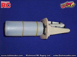
| 1.25.4.1.8. VMA-E240X Easy 3D 45-52 ARF - Modify the Fixed Firewall in the Fuselage. | ||||
Use Template C. Use scissors to trim to the outer perimeter of the fuselage as shown on Template C. Cut out the inner area of Template C that is bound by the black line. The black line denotes the fixed firewall installed by the factory for electric power systems. Carefully, center, align and attach template C to the forward face of the fixed firewall of the fuselage using adhesive from a glue stick.
Use a Dremel tool and sanding drum to carve away the fixed firewall to match the red line perimeter of Template C. Work in small steps and test the fit of your power module assembly frequently. Continue carving in small steps with frequent test fits until the fuel tank can be easily inserted into the fuselage from the front and the back face of the power module firewall can be pressed flush against the forward face of the fixed firewall while the power module firewall is centered and aligned.
|
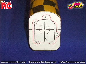
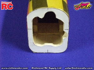
| 1.25.4.1.9. VMA-E240X Easy 3D 45-52 ARF - Temporarily Attach the Power Module to the Fuselage. |
Use two button head sheet metal screws to temporarily hold the power module centered and flush fitted to the front of the fuselage. This will enable you to attach the engine and check the cowl and muffler fit before completing the permanent installation of the power module firewall. We strongly suggest drilling pilot holes for the screws to prevent splitting wood in the fuselage.
|
| 1.25.4.1.10. VMA-E240X Easy 3D 45-52 ARF - Install Engine, Cowl, Muffler, Spinner & Throttle Control | ||
See Step 15 of the Assembly and Operations Manual to install your engine, cowl, muffler and spinner. Use a Dremel drum sander and sharp scissors to cut out the cowl to fit your engine. Use Template D as a guide for cutting the cowl. Install your muffler and check the muffler clearances through the cowl and around the fuselage. Use an exhaust stack extender if necessary to enable the muffler to clear the fuselage.
See Step 19 of the Assembly & Operations Manual for routing and connection of the Throttle Control.
|
| 1.25.4.1.11. VMA-E240X Easy 3D 45-52 ARF - Finalize Attachment of the Power Module to the Fuselage. |
After test fitting your engine, cowl, muffler and spinner you are ready to finalize the attachment of the power module to the fuselage.
There are two general ways to go about this, removeable or non-removeable.
If you want to be able to remove the power module for maintenance etc in the future we suggest using four button head sheet metal screws (four #8 x 5/8 Robertson screws provided). Use screws that are just long enough to go through the firewalls but not protrude into the fuel tank area. Choose the screw down points carefully to pick good solid widely distributed areas. Drill pilot holes through both firewalls being careful not to nick or hole the fuel tank.
Wick Pacer ZAP CA into the holes in the fuselage to toughen them up.
Firmly attach the power module to the fuselage using the screws.
If you want to permanently attach the power module to the fuselage, use Pacer 30 Minute ZEPOXY. Apply plenty of ZEPOXY to both the power module firewall and the fixed firewall. Flush the firewalls together ensuring that everything is aligned properly. Hold in place with masking tape or screws for several hours.
Clean away excess expoxy before it cures.
|
| 1.25.4.1.12. Support |
On Line, eMail, Fax, Phone, Mail |
| We offer the Best in Support Services. |
We back up our products and our customers with the best support services available. From our industry leading Knowledge Base to information about your Shipment, we've got you covered!
To access our Support Services please:
Your Choice of Support Services that Work for You:
|
| 1.25.4.1.12.1. Contact Us |
For Sales and other Inquiries |
| Support - Contact Us - Reach our Sales Department by eMail, Fax, Phone or Mail |
Technical Inquiries: Please review the information provided in our Knowledge Base. After checking our Knowledge Base, if you need further assistance please use our Submit A Question service to get a response within 2 Business Days.
Sales Inquiries: Please note that our Sales Department personnel are trained and dedicated to:
Their depth of technical knowledge is about on par with what is shown in our printed sales literature. In most cases, they are working from the same printed advertisements or content from our web site that you are. Asking sales personnel to confirm the size, color and availability of a product is well within their capabilities. However, asking detailed questions about technical issues is not.
Buy our Products:
For All Other Inquiries... please consult the following resources:
|
| 1.25.4.1.13. Keep Up to Date |
Check Frequently for Updates |
| Support - Stay Current - Check Frequently for Updated &/or Additional Information |
This information is subject to change without notice. When viewing this information in a printed form the printing date will be visible in the lower right corner. Check frequently for updates &/or Additional Information.at www.richmondrc.com, > Enter the Site, > Support Services, follow the links to our Knowledge Base. Review the Table of Contents and search for the name and/or part number of this product.
For automated notification of changes to information contained in our Knowledge Base please register as a Priority Response member and subscribe to our Priority Response Notification Service.
|
| 1.26. VMA-E260X Extra 330L 45-61 ARF ECS Sport |
| 1.26.1. VMA-E260X Extra 330L 45-61 ARF - Assembly & Operations Manual in PDF format |
| 1.26.2. VMA-E260X Extra 330L 45-61 ARF - CG - Where is it located? Is the manual correct? |
Question: Where is the CG located on the VMAR Extra 330L 45-60 ARF ECS? Answer: In stage 29 on page 15 of the manual there is a diagram and information as follows: The CG is located 4.75-5.25 inches (120-130 mm) back from the leading edge of the wing. This information is correct. Additional Information: This is an aerobatic model. It is designed for aerobatics and is inherently less stable than a high wing trainer. The CG location affects its ability to do aerobatics. Setting the CG further forward will make the model more stable (easier to fly) but will limit it's ability to do aerobatics. Flyers who are unfamiliar with flying an Extra 330L OR who wish to test the model initially in a more stable configuration may wish to move the CG further forward for the first few flights. The CG can be moved ahead to lie up to 1/2" (12 mm) forward of the thickest part of the wing. This will be a more stable less aerobatically capable configuration. After becoming confident and more familiar with the flying characteristics the CG can be moved further aft towards the recommended location. |
| 1.26.3. VMA-E260X Extra 330L 45-61 ARF - Plastic Wing Root Pieces - What are they for? |
Question: I found two plastic pieces that appear to match the shape of the wing roots. What are these for? Answer: These are a bonus component that was added to this model. Usually they appear on one "sheet" of plastic and can be cut out and mounted by the modeler after assembly. These are wing root fairings or covers and serve to provide a cleaner seal between the wing roots and the sides of the fuselage. They can be cut a bit large initially and then trimmed to fit. Supplementary Information: Are they absolutely necessary? No they are not. They provide a better seal and look nice but they are not mandatory for flight. What adhesive should I use to mount these? Always test any adhesive on a small out of view area of any painted or plastic component before proceeding. We generally recommend Pacer Dap-A-Goo for this type of component in this type of application. Dap-A-Goo is a silicone like material that has a solvent base rather than acetic acid and it dries quickly, fuel proof, relatively clear and best of all it sticks to just about any plastic and stays slightly flexible. Remember... ALWAYS TEST FIRST! |
| 1.26.4. VMA-E260X Extra 330L 45-61 ARF - Template for Cowl Decal Placement |
When placing the decals on the VMA-E260X Extra 330L cowl it may be helpful to use the template provided below as an attachment.
|
| 1.26.5. ZBO-Y190611A More Information | ||||||||||||||||||
More Information about #ZBO-Y190611A ... BLOWOUT - VMAR EXTRA 330L 45-61 ARF (RED) - FINAL SALE This is a BLOWOUT... FINAL SALE item and the following caution applies:
No other information is available regarding #ZBO-Y190611A BLOWOUT - VMAR EXTRA 330L 45-61 ARF (RED) - FINAL SALE. |
| 1.27. VMA-E340X Escape 40-52 ARF ECS Low Wing Trainer - Various Colors |
Question: I am about to install the vertical stabilizer into my Escape. I find that when I am dry fitting and testing the installation of the vertical stabilizer before gluing that the rudder prevents full deflection of the elevator. The notch in the rudder that is intended to provide sufficent clearance appears to be slightly too high when viewed with the model top side up. What do I do? Answer: This is a problem on some early production Escapes produced prior to 20050426. Enlarge the clearance slot in the rudder by about 1/8" expanding it downwards. This should be done BEFORE the vertical stabilizer is installed. Do NOT modify the elevator. See more information below. More Information: See the attached picture. The Red tinted area should be cut away using a very sharp #11 blade OR preferably a powered fine blade scroll saw. Remove only about half of what is shown in the red tinted area and then do another trial fit. Only cut away more if you have to. Do NOT exceed the size of the red tinted area which as shown denotes removing a total of about 1/8" of material to expand the bottom limit of the cut out in the rudder. After expanding the clearance hole in the rudder, wick thin CA such as ZAP CA from PACER into the wood edges of the cutout. Let the CA soak well into the wood. Do two applications. This will stiffen and significantly strengthen the wood. Now remove the covering from the pre-drilled rudder control horn hole represented by the blue circle in the picture (hold the rudder up to a light source to illuminate the hole if cannot locate it). Once the covering has been removed from both sides of the hole, wick thin CA into the edges of the hole. Let the CA soak well into the wood. Do two applications. After the wood has been reinforced with CA, install the rudder control horn. Note carefully which way around you want to do this. Make sure that you have the control horn coming out the correct side of the rudder so that it connects to the rudder control rod. Seat the control horn firmly into the hole. You want a snug fit but do not overtighten. Remember that this is a model airplane not a Sherman Tank... no pipe wrenches please! After you have installed the control horn, again check that is correctly positioned and that it engages with the rudder control rod. Only after you are satisfied that the control horn is correctly positioned and snugly tight, then wick more CA or even better CA+ down the sides of the white T nut that is on the opposite side of the rudder. You want to fill any gap in the hole around the T-Nut so that there is one integral bond between the T-nut and the wood surrounding it. Now you are ready to use 30 Minute Epoxy to glue the vertical stabilizer into place AFTER you do one more check on alignment, clearances etc. What to do if you have already glued the Vertical Stabilizer into place before you noticed the lack of clearance? Well it would have been best to check things out during the dry fit before you glued it into place BUT all is not lost. Review the information above and the picture attached. Then do what is described but you have to do the modification "in situ" i.e. in place. It's the same procedure just a bit more difficult to manage. Go slowing and carefully and use a shart #11 blade. |
| 1.28. VMA-F210X Fournier RF4D 2000 ARF ECS Electric - Various Colors |
Technical Information related to the VMAR Fournier RF4D 2000 ARF ECS Electric
|
| 1.28.1. VMA-F210X Fournier RF4D 2000 ARF ECS Electric - Assembly & Operations Manual in PDF format |
| 1.28.2. VMA-F210X Fournier RF4D 2000 ARF ECS Electric - Specifications | ||||||||||||||||||||
|
| COPYRIGHT |
Copyright Richmond RC Supply Ltd. All rights reserved.
|
| 1.28.3. VMA-F210X Fournier RF4D 2000 ARF ECS Electric - Spinner |
Various pictures of the VMAR Fournier and picture 12i on Page 7 of the Assembly & Operations Manual show a small spinner installed on the model. This spinner was included by the manufacturer into some of the first production run, primarily the blue version of the model. The spinner was subsequently NOT included with later production runs of what were mainly the red version of the model. If you find a spinner included with your model of the VMAR Fournier, we recommend NOT installing the spinner or it's related backing plate. It is difficult to install the spinner and backing plate in a secure and balanced manner. If your model did include a spinner (most do not) and you wish to install the spinner and backing plate, take extra care to ensure that they are securely held in place and balanced to keep vibration to a minimum. |
| COPYRIGHT |
Copyright Richmond RC Supply Ltd. All rights reserved.
|
| 1.29. VMA-F35X08 Floats 40 ARF for 06-10 lbs (40-60) Models |
202004018... noted that the F32x07 version has been superceded by the F35x08 version. The F35x08 version is approx 3 inch longer and 1 inch wider than the F32x07 version. Whereas the F32x07 version was rated for 05-09 lbs, the F35x08 version is rated for 06-10 lbs. The Assembly & Operations manual remains the same. |
| 1.29.1. What is the difference between the various versions of the 05-09lb float sets. How to Adapt? |
Question: What is the difference between (20200418... edits above...
Since 20050101 the Beaver 40-60 ARF has four holes predrilled in the bottom of the fuselage for the standard main gear set that comes with the Beaver 40-60 ARF. The spacing of the holes in the bottom of the fuselage may not match the holes in the mounting bracket that comes with your floats. If it matches, you are good to go... if it does not match, four new holes will have to be drilled... this is not a big job if you follow the procedure outlined below. Procedure: Remove the forward mounting bracket from the float box. Turn the fuselage upside down and locate the pre-drilled holes in the bottom of the fuselage. Hold the mounting bracket with the flat non-tapered edge facing the engine end of the fuselage. Check the holes in the bracket vs the holes in the fuselage. If they match, attach the bracket to the fuselage with the screws provided. If they do not match, carefully center the mounting bracket and mark the location of the bracket holes on the fuselage using a ball point pen. Remove the bracket and examine the four pen marks. Plug the factory drilled holes in the fuselage with clear or white silicone. Use a 3/32" drill bit to make four new holes in the fuselage at the loction of the pen marks. Turn the fuselage upright and note the location of the four new holes in the landing gear flat plate in the bottom of the fuselage. Locate the extra flat plate provided with the floats. Epoxy this plate into place inside the fuselage on top of the four holes you drilled. Let the Epoxy dry. Now turn the fuselage back over and drill the four holes again. Attach the front bracket for the floats (flat non-tapered edge facing forward) to the fuselage with the four screws provided. |
| 1.29.2. Floats - Hard Point Area... Can it be Moved? |
Question: I want to adapt the VMAR Floats to fit on my model. Can I move the hard point attachment locations on the floats?
Answer: The hard point attachment points on the floats should not be moved. If you need to change the relative position of the floats with respect to your model (to position the step with respect to the CG for example) we recommend adding or relocating hard point locations within the fuselage of the model rather than modifying the floats. |
| 1.30. VMA-F40X12 Floats 60-90 ARF for 09-15 lbs (60-90) Models |
20200418 |
| 1.30.1. Floats - Hard Point Area... Can it be Moved? |
Question: I want to adapt the VMAR Floats to fit on my model. Can I move the hard point attachment locations on the floats?
Answer: The hard point attachment points on the floats should not be moved. If you need to change the relative position of the floats with respect to your model (to position the step with respect to the CG for example) we recommend adding or relocating hard point locations within the fuselage of the model rather than modifying the floats. |
| 1.31. VMA-F490X Phantom II 60-90 Jet (Prop) ARF 3DS - USAF and USN |
| 1.31.1. VMA-F490X Phantom II - Balancing for Correct CG Location - Adding Weight |
Question: Should I expect to add weight to the VMAR Phantom in order to have the CG in the correct location? If I must add weight, where will it normally go and how much do you think I will need? Answer: This will depend on the weight of your engine, servos, receiver and in particular the weight and location of your airborne battery pack. Additional Information: The VMAR Phantom accomodates two stroke engines in the .60-.91 size range. As of 2005, engines in this class are often built from the same casing and although the crankshaft may be a bit heavier in a .91 the case is a bit lighter. Hence, in many brands there is not much of a weight difference between a .60 and a .91 two stroke engine. Many popular engines in this class weigh, with muffler, approximately 24 oz. Radio receivers generally do not vary in weight much between brands. Servos can vary in weight from servo to servo(ball bearing heavy duty servos weigh more than standard servos) and airborne battery packs can be significantly different depending on their voltage and mAh capacity. Experience with a variety of standard servos, 4.8V-6.0V nicad packs and .60-.91 size two stroke engines weighing approximately 24 oz with muffler has shown that for first flights 6-8 oz of weight in the tail is needed for a CG location that is somewhat nose heavy. After first flights moving the CG back slightly within the recommended range may be desired and require 10-12 ounces of weight in the tail. These guidelines are NOT considered to be suitable for all situations. If your engine is heavier than 24 ounces, you may need more weight in the tail. If you are using a 6.0V 2000 mAh airborne battery located in the aft end of the model you may need less additional weight in the tail than if you are using a 4.8V 600mAh battery. Each model should be carefully checked for CG and compared with the recommended CG location. First flights should be slightly nose heavy (forward CG location) and no model should be flown with a CG outside the recommended range. |
| 1.31.2. VMA-F490X Dummy Fuel Tanks - Is it Ok to Fly with them? |
Question: I have the VMAR Phantom 90+ ARF. The Phantom comes with set of Dummy Wing Tanks. Is it OK to fly the Phantom with the Dummy Wing Tanks in place? Answer: Yes they are airworthy and you can fly the Phantom with the Dummy Wing Tanks in place. |
| 1.31.3. VMA-F490X Electric Power? Can it be done? | |||||||
| |||||||
| 1.31.4. VMA-F490X Phantom II - Engine Sizes - Will it fly OK on a .60? |
Question: Will the VMAR Phantom II fly OK on a .60? What do you recommend? Answer: We recommend a .60 to .91 two stroke engine. Yes it flys well on a .61. A .75-.91 would be the best overall choice... .91 is the max and a bit over the top but favored by flyers who like power. Anything larger than a .91 will require considerable work on the fuselage nose section and you run the risk of detracting from the scale like appearance if you butcher the nose area. This model is NOT intended to accomodate four stroke engines. Please note that we have NOT tested this model with two strokes larger than a .91 and have NOT tested this model with four strokes. We recommend the use of a .60 to .91 two stroke engine for this model. We are not able to endorse the use of two stroke engines larger than a .91 or the use of four stroke engines for this model.
|
| 1.31.5. VMA-F490X Phantom II - Exhaust Outlets - Fit |
Question: Do I trim the open end of the exhaust outlets to fit over the factory installed "circles" that are attached to the rear of the fuselage?
|
| 1.31.6. VMA-F490X Phantom II - Oleo Strut Sets - Are They Available? |
Question: Are there oleo strut sets available for the VMAR Phantom II 60-91 ARF? Are they actually functional or just dummies? Answer: The VMAR Phantom II 60-91 ARF comes standard with fixed gear and we offer a set of oleo struts (3) for this model. Yes they are functional and easy to install. They are well made, work well, look very scale like and help protect your model from damage by sucking up hard landings and rough fields. These oleo strut sets are very economical and we offer them at a very low combo price to anyone buying them with the Phantom. See the VMAR On Line store at www.richmondrc.com . Look just below the Jets listing in the left frame. This combo offer is open to all owners of VMAR Phantom II 60-90 ARF's until the end of 2006... regardless of when or where the model was purchased. For oleo strut installation instructions please click the following: Installation Tips - VMA-OLEOxxx Oleo Strut Sets [New Window] |
| 1.31.7. VMA-F490X Phantom II - Retract Recommendations |
Question: If I want to install optional retracts in the VMAR Phantom II 60-91 ARF which retracts should I use? Answer: The VMAR Phantom II 60-91 ARF comes standard with fixed gear and it is ready to accept Robart mechanical retracts. Robart #608HD main gear retracts and the Robart #610 nose gear retract have been installed and tested in this model. Other brands of medium duty retracts can, with work be fitted. Please see the instructions that come with your retracts for specific installation instructions and requirements. |
| 1.31.8. VMA-F490X Phantom II - Retract Servo Requirements |
Question: How many servos are needed if I want to install optional mechanical retracts in the VMAR Phantom II 60-91 ARF? Answer: 2 standard servos for the mains and 1 standard servo for the nose gear. We recommend the use of Airtronics servos.
|
| 1.31.9. VMA-F490X Phantom II - Rudder Control Rod - Fit |
Question: Is the control rod in the rudder of the VMAR Phantom II supposed to be a very tight fit or a slightly loose fit? Answer: The control rod in the rudder of the VMAR Phantom II is intended to have a slightly loose fit until the vertical stabilizer is installed into the fuselage per the assembly and operations manual. Once installed per the manual, the control rod will have a tighter fit. After installation, always ensure that the control rod and rudder move freely with a standard servo. |
| 1.32. VMA-F590X F5E Tiger II 60-91 Jet (Prop) ARF 3DS - Camo & Grey |
| 1.32.1. VMA-F590X F5E Tiger II 60-91 Jet (Prop) ARF - READ ME FIRST |
PLEASE READ ME FIRST BEFORE PROCEEDING TO ASSEMBLE OR OPERATE THIS PRODUCT |
| LIABILITY DISCLAIMER & COPYRIGHT NOTICE |
LIABILITY DISCLAIMER The authors and/or suppliers and/or disseminaters of this information and/or product expressly disclaim any warranties or representations, either expressed or implied, including but not limited to implied warranties of fitness, accuracy, timeliness or applicability of the information and/or product provided here. In no event will the authors and/or suppliers and/or disseminaters of this information and/or product have any obligation arising from contract or tort, for loss of revenue or profit, or for indirect, special, incidental, consequential or other damages of any sort arising from this information and/or product. In using this information and/or product, the user accepts all responsibility for and all liability associated with such use. PROCEEDING WITH THE USE OF THIS INFORMATION AND/OR PRODUCT INDICATES AGREEMENT WITH AND ACCEPTANCE OF THE LIABILITY DISCLAIMER.
|
| Please Note the following Caution |
CAUTION A Remote Control (RC) model aircraft is not a toy. It is a flying model that functions much like a full size airplane. If you do not assemble and operate model aircraft properly you can cause injury to yourself and others and damage property. DO NOT FLY a model aircraft unless you are qualified. You are ultimately responsible for the mechanical, aeronautical and electrical integrity of any model you fly and all of the components that make up the model including but not limited to the airframe itself, control surfaces, hinges, linkages, covering, engine, motor, radio, servos, switches, wiring, battery and parts. Check all components before and after each flight. It is essential that you act with the clear understanding that you are solely responsible for all aspects of the model at all times. DO NOT FLY until it is right.
|
| 1.32.1.1. VMA-F590X F5E Tiger II 60-91 Jet (Prop) ARF - General Information |
| COPYRIGHT |
Copyright Richmond RC Supply Ltd. All rights reserved.
|
| Tips for Avoiding Common Problems |
We have supplied thousands and thousands and thousands of model aircraft in the past 20 plus years. We're not bragging! We tell you this to give some credibility to our suggested list of tips that follow. In talking to modelers around the world, here is what we have found is the key to... AVOIDING 90% of PROBLEMS that can arise:
|
| 1.32.1.2. VMA-F590X F5E Tiger II 60-91 Jet (Prop) ARF - Supplement to the Manual |
| COPYRIGHT |
Copyright Richmond RC Supply Ltd. All rights reserved.
|
| 1.32.1.2.1. VMA-F590X F5E Tiger II 60-91 ARF - Control Horns |
|
| Control Horn Installation - How to |
Question: How are VMAR control horns installed? The iillustration below and to the left shows a control horn set before installation. Note 5 parts make up the set. In Light Duty applications the Metal Nut may not be included and only 4 parts will make up the set. The illustration below and to the right shows a control horn set partially installed. Although illustrations in various manuals show the bevelled washer with the bevel pointing away from the surface we find that we get a cleaner strong installation with the bevel pointing inwards. We recommend wicking thin CA such as Pacer ZAP/CA (Pink) into the exposed wood surrounding the hole in the control surface. This helps further strengthen the wood. This is not a requirement but if you are pushing the power limits or planning on extreme aerobatics or speeds, the extra strength could come in handy. Use two applications of thin CA 1 minute apart, BEFORE installing the control horn.
The illustration below shows horn side view of a control horn set fully installed. The illustration to the left is a lighter duty application without the metal nut. The illustration to the right shows a heavier duty application with the metal nut installed. If the metal nuts have been supplied with the horns, we recommend using them.
|
| 1.32.1.2.2. VMA-F590X F5E Tiger II 60-91 ARF - Elevator Servo Mounts |
PLEASE NOTE:
Before installing your elevator servos, ensure that the elevator servo mounts are securely attached to the surface of the horizontal stabilizer..
If the mounts appear to have been factory installed, you should consider the mounts to be only tacked into place to indicate positioning. Carefully secure the servo mounts to the horizontal stabilizer using 30 minute epoxy or good quality medium CA+ such as ZAP-A-GAP.
|
| 1.32.1.3. VMA-F590X F5E Tiger II 60-91 Jet (Prop) ARF - Important Information |
| COPYRIGHT |
Copyright Richmond RC Supply Ltd. All rights reserved.
|
| 1.32.1.3.1. VMA-F590X F5E Tiger II 60-91 Jet (Prop) ARF - Covering |
This model uses VCOTE2 - 3DS Covering |
| VCOTE2-3DS - Care & Maintenance - Quick Tips |
|
Question: Do you have any pointers regarding the Care & Maintenance of VCOTE2 - 3DS? Answer: Yes we have this Summary of Quick Tips and at www.richmondrc.com ( Enter Site > Support > Knowledge Base then Search on "Covering") we have an expanded explanation for each of these Tips. VCOTE2 - 3DS is a proprietary covering system engineered in Canada & available only from VMAR. Please note that VCOTE2 - 3DS is NOT Monokote or Solarfilm, its different. As with any new modern technology, the maintenance methods may be different than those you used with your older covering so its important to read the Tips over FIRST. Whatever you want to do with VCOTE2 - 3DS, test it on a small out of the way area first. Here is our Summary of Quick Tips related to VCOTE2 - 3DS covering.
|
| 1.32.1.4. Support |
On Line, eMail, Fax, Phone, Mail |
| We offer the Best in Support Services. |
We back up our products and our customers with the best support services available. From our industry leading Knowledge Base to information about your Shipment, we've got you covered!
To access our Support Services please:
Your Choice of Support Services that Work for You:
|
| 1.32.1.4.1. Contact Us |
For Sales and other Inquiries |
| Support - Contact Us - Reach our Sales Department by eMail, Fax, Phone or Mail |
Technical Inquiries: Please review the information provided in our Knowledge Base. After checking our Knowledge Base, if you need further assistance please use our Submit A Question service to get a response within 2 Business Days.
Sales Inquiries: Please note that our Sales Department personnel are trained and dedicated to:
Their depth of technical knowledge is about on par with what is shown in our printed sales literature. In most cases, they are working from the same printed advertisements or content from our web site that you are. Asking sales personnel to confirm the size, color and availability of a product is well within their capabilities. However, asking detailed questions about technical issues is not.
Buy our Products:
For All Other Inquiries... please consult the following resources:
|
| 1.32.1.5. Keep Up to Date |
Check Frequently for Updates |
| Support - Stay Current - Check Frequently for Updated &/or Additional Information |
This information is subject to change without notice. When viewing this information in a printed form the printing date will be visible in the lower right corner. Check frequently for updates &/or Additional Information.at www.richmondrc.com, > Enter the Site, > Support Services, follow the links to our Knowledge Base. Review the Table of Contents and search for the name and/or part number of this product.
For automated notification of changes to information contained in our Knowledge Base please register as a Priority Response member and subscribe to our Priority Response Notification Service.
|
| 1.32.2. VMA-F590X F5E Tiger II 60-91 Jet (Prop) ARF - Additional Information |
In general "Additional" Information is:
Subject to the Conditions of Use, please review the attachments and related articles listed below. |
| COPYRIGHT |
Copyright Richmond RC Supply Ltd. All rights reserved.
|
| 1.32.2.1. VMA-F590X F5E Tiger II 60-91 Jet (Prop) ARF - Missile Set - Is it Included? |
Question: Does a dummy missile set come with the VMAR F5E? Answer: Yes, a dummy missile set comes with the VMAR F5E. |
| 1.32.2.2. VMA-F590X F5E Tiger II 60-91 Jet (Prop) ARF - Oleo Struts - Available or Not? |
Question: Does the VMAR F5E support the use of functional Oleo Struts? Answer: Yes. The VMAR F5E supports the use of functional Oleo Struts. The VMAR Oleo Strut set is #VMA-OLEO2S3. The Oleo Strut set includes two oleos for the main gear and one for the nose. It also includes the wheels, axles and wheel retainers. |
| 1.32.2.3. VMA-F590X F5E Tiger II 60-91 Jet (Prop) ARF - Retract Ready? |
Question: Is the VMAR F5E retract ready? Answer: Yes the VMAR F5E is retract ready. We include nicely machined fixed gear and have pre-arranged the structure to accomodate easy installation of third party retracts.
|
| 1.32.2.4. VMA-F590X F5E Tiger II 60-91 Jet (Prop) ARF - Retract Recommendations? |
Question: If I want to install optional retracts in the VMAR F5E Tiger II 60-91 ARF which retracts should I use? Answer: The VMAR F5E Tiger II 60-91 ARF comes standard with fixed gear and it is ready to accept Robart mechanical retracts. Robart #608HD main gear retracts and the Robart #610 nose gear retract have been installed and tested in this model. Other brands of medium duty retracts can, with work be fitted. Please see the instructions that come with your retracts for specific installation instructions and requirements. |
| 1.32.3. VMA-F590X F5E Tiger II 60-91 Jet (Prop) ARF - Assembly & Operations Manual in PDF format |
| 1.32.4. VMA-F590X F5E Tiger II 60-91 Jet (Prop) ARF - Pictures, Graphics & Artwork |
| 1.32.4.1. Logo VMA-F590X F5E Tiger II 60-91 Jet (Prop) ARF |
| 1.32.4.1.1. Logo (CMYK_TIF) VMA-F590X F5E Tiger II 60-91 Jet (Prop) ARF |
| 1.32.4.2. Pictures VMA-F590G F5E Hornet 60-91 Jet (Prop) ARF - Gray |
| 1.32.4.2.1. Pictures (CMYK_TIF) VMA-F590G F5E Tiger II 60-91 Jet (Prop) ARF - Gray |
| 1.32.4.3. Pictures VMA-F590U F5E Tiger II 60-91 Jet (Prop) ARF - Camo |
| 1.32.4.3.1. Pictures (CMYK_TIF) VMA-F590U F5E Tiger II 60-91 Jet (Prop) ARF - Camo |
| 1.33. VMA-F690X F18 Hornet 60-91 JET (PROP) ARF 3DS - Blue & Navy |
| 1.33.1. VMA-F690X F18 Hornet 60-91 Jet (Prop) ARF - READ ME FIRST |
PLEASE READ ME FIRST BEFORE PROCEEDING TO ASSEMBLE OR OPERATE THIS PRODUCT
|
| LIABILITY DISCLAIMER & COPYRIGHT NOTICE |
LIABILITY DISCLAIMER The authors and/or suppliers and/or disseminaters of this information and/or product expressly disclaim any warranties or representations, either expressed or implied, including but not limited to implied warranties of fitness, accuracy, timeliness or applicability of the information and/or product provided here. In no event will the authors and/or suppliers and/or disseminaters of this information and/or product have any obligation arising from contract or tort, for loss of revenue or profit, or for indirect, special, incidental, consequential or other damages of any sort arising from this information and/or product. In using this information and/or product, the user accepts all responsibility for and all liability associated with such use. PROCEEDING WITH THE USE OF THIS INFORMATION AND/OR PRODUCT INDICATES AGREEMENT WITH AND ACCEPTANCE OF THE LIABILITY DISCLAIMER.
|
| Please Note the following Caution |
CAUTION A Remote Control (RC) model aircraft is not a toy. It is a flying model that functions much like a full size airplane. If you do not assemble and operate model aircraft properly you can cause injury to yourself and others and damage property. DO NOT FLY a model aircraft unless you are qualified. You are ultimately responsible for the mechanical, aeronautical and electrical integrity of any model you fly and all of the components that make up the model including but not limited to the airframe itself, control surfaces, hinges, linkages, covering, engine, motor, radio, servos, switches, wiring, battery and parts. Check all components before and after each flight. It is essential that you act with the clear understanding that you are solely responsible for all aspects of the model at all times. DO NOT FLY until it is right.
|
| 1.33.1.1. VMA-F690X F18 Hornet 60-91 Jet (Prop) ARF - General Information |
|
| COPYRIGHT |
Copyright Richmond RC Supply Ltd. All rights reserved.
|
| Tips for Avoiding Common Problems |
We have supplied thousands and thousands and thousands of model aircraft in the past 20 plus years. We're not bragging! We tell you this to give some credibility to our suggested list of tips that follow. In talking to modelers around the world, here is what we have found is the key to... AVOIDING 90% of PROBLEMS that can arise:
|
| 1.33.1.2. VMA-F690X F18 Hornet 60-91 Jet (Prop) ARF - Supplement to the Manual |
| COPYRIGHT |
Copyright Richmond RC Supply Ltd. All rights reserved.
|
| 1.33.1.2.1. VMA-F690X F18 Hornet 60-90 ARF - Control Horns |
|
| Control Horn Installation - How to |
Question: How are VMAR control horns installed? The iillustration below and to the left shows a control horn set before installation. Note 5 parts make up the set. In Light Duty applications the Metal Nut may not be included and only 4 parts will make up the set. The illustration below and to the right shows a control horn set partially installed. Although illustrations in various manuals show the bevelled washer with the bevel pointing away from the surface we find that we get a cleaner strong installation with the bevel pointing inwards. We recommend wicking thin CA such as Pacer ZAP/CA (Pink) into the exposed wood surrounding the hole in the control surface. This helps further strengthen the wood. This is not a requirement but if you are pushing the power limits or planning on extreme aerobatics or speeds, the extra strength could come in handy. Use two applications of thin CA 1 minute apart, BEFORE installing the control horn.
The illustration below shows horn side view of a control horn set fully installed. The illustration to the left is a lighter duty application without the metal nut. The illustration to the right shows a heavier duty application with the metal nut installed. If the metal nuts have been supplied with the horns, we recommend using them.
|
| 1.33.1.2.2. VMA-F690X F18 Hornet 60-90 ARF - Horizontal Stabilizer Fit - Page 6, Figure 6D |
This supplementary information applies to manuals with a copyright date of 20060822 (see back cover). Manuals having later copyright dates may already reflect this supplementary information. Please see Page 6, Figure 6D. Figure 6D shows the fitting of the horizontal stabilizers into the horizontal stabilizer slots in the side aft section of the fuselage. The horizontal stabilizers fit into the slots in the fuselage and are to be seated securely into their respective fuselage slots in the same manner for both the left and right horizontal stabilizers. The distances shown in Figure 6D of the 20060822 version of the manual are incorrect. The "leading edge" distance (bottommost in the picture) should be approximately 16.14 in. (410 mm) and the "hinge line" distance (uppermost in the picture) should be approximately 13.31 in. (338 mm). These distances may vary slightly in production. The important point to note here is that the two horizontal stabilizers should be seated securely into their respective fuselage slots in the same manner for both the left and and right horizontal stabilizers. The actual distances are not as critical as the requirements that:
|
| 1.33.1.2.3. VMA-F690X F18 Hornet 60-90 ARF - Vertical Stabilizer Fit - Page 5, Figure 5C |
This supplementary information applies to manuals with a copyright date of 20060822 (see back cover). Manuals having later copyright dates may already reflect this supplementary information. Please see Page 5, Figure 5C. Step 5.1 and Figure 5C describe and show the dry test fitting of the vertical stabilizers into the vertical stabilizer slots in the top aft section of the fuselage. The vertical stablizers fit into the slots in the fuselage and are to be seated securely into their respective fuselage slots in the same manner for both the left and right vertical stabilizers. The distances shown in Figure 5C of the 20060822 version of the manual are incorrect. The "leading edge" distance (rightmost in the picture) should be approximately 13.58 in. (345 mm) and the "hinge line" distance (leftmost in the picture) should be approximately 11.02 in. (280 mm). These distances may vary slightly in production. The important point to note here is that the two vertical stabilizers should be seated securely into their respective fuselate slots in the same manner for both the left and and right vertical stabilizers. The actual distances are not as critical as the requirements that:
|
| 1.33.1.3. VMA-F690X F18 Hornet 60-91 Jet (Prop) ARF - Important Information |
|
| COPYRIGHT |
Copyright Richmond RC Supply Ltd. All rights reserved.
|
| 1.33.1.3.1. VMA-F690X F18 Hornet 60-91 Jet (Prop) ARF - Covering |
This model uses VCOTE2 - 3DS Covering |
| VCOTE2-3DS - Care & Maintenance - Quick Tips |
|
Question: Do you have any pointers regarding the Care & Maintenance of VCOTE2 - 3DS? Answer: Yes we have this Summary of Quick Tips and at www.richmondrc.com ( Enter Site > Support > Knowledge Base then Search on "Covering") we have an expanded explanation for each of these Tips. VCOTE2 - 3DS is a proprietary covering system engineered in Canada & available only from VMAR. Please note that VCOTE2 - 3DS is NOT Monokote or Solarfilm, its different. As with any new modern technology, the maintenance methods may be different than those you used with your older covering so its important to read the Tips over FIRST. Whatever you want to do with VCOTE2 - 3DS, test it on a small out of the way area first. Here is our Summary of Quick Tips related to VCOTE2 - 3DS covering.
|
| 1.33.1.4. Support |
On Line, eMail, Fax, Phone, Mail |
| We offer the Best in Support Services. |
We back up our products and our customers with the best support services available. From our industry leading Knowledge Base to information about your Shipment, we've got you covered!
To access our Support Services please:
Your Choice of Support Services that Work for You:
|
| 1.33.1.4.1. Contact Us |
For Sales and other Inquiries |
| Support - Contact Us - Reach our Sales Department by eMail, Fax, Phone or Mail |
Technical Inquiries: Please review the information provided in our Knowledge Base. After checking our Knowledge Base, if you need further assistance please use our Submit A Question service to get a response within 2 Business Days.
Sales Inquiries: Please note that our Sales Department personnel are trained and dedicated to:
Their depth of technical knowledge is about on par with what is shown in our printed sales literature. In most cases, they are working from the same printed advertisements or content from our web site that you are. Asking sales personnel to confirm the size, color and availability of a product is well within their capabilities. However, asking detailed questions about technical issues is not.
Buy our Products:
For All Other Inquiries... please consult the following resources:
|
| 1.33.1.5. Keep Up to Date |
Check Frequently for Updates |
| Support - Stay Current - Check Frequently for Updated &/or Additional Information |
This information is subject to change without notice. When viewing this information in a printed form the printing date will be visible in the lower right corner. Check frequently for updates &/or Additional Information.at www.richmondrc.com, > Enter the Site, > Support Services, follow the links to our Knowledge Base. Review the Table of Contents and search for the name and/or part number of this product.
For automated notification of changes to information contained in our Knowledge Base please register as a Priority Response member and subscribe to our Priority Response Notification Service.
|
| 1.33.2. VMA-F690X F18 Hornet 60-91 Jet (Prop) ARF - Additional Information |
In general "Additional" Information is:
Subject to the Conditions of Use, please review the attachments and related articles listed below. |
| COPYRIGHT |
Copyright Richmond RC Supply Ltd. All rights reserved.
|
| 1.33.2.1. VMA-F690X F18 Hornet 60-91 Jet (Prop) ARF - Missile Set - Is it Included? |
Question: Does a dummy missile set come with the VMAR F18? Answer: A dummy missile set comes with the Navy Version of the VMAR F18. The Blue Angels version does NOT come with a missile set. The Blue Angels version is modeled after the aircraft used by the Blue Angels precision flying team where missiles are not permitted. |
| 1.33.2.2. VMA-F690X F18 Hornet 60-91 Jet (Prop) ARF - Oleo Struts - Available or Not? |
Question: Does the VMAR F18 support the use of functional Oleo Struts? Answer: Yes. The VMAR F18 includes VMAR Oleo Strut set #VMA-OLEO6S3. These are included with the kit and available as aftermarket replacements. The Oleo Strut set includes two oleos for the main and one for the nose. It also includes the wheels, axles and wheel retainers. |
| 1.33.2.3. VMA-F690X F18 Hornet 60-91 Jet (Prop) ARF - Oleo Strut Nose Gear - Functional or Not? |
Question: Is the steerable nose gear assembly for the VMAR F18 actually a functional Oleo strut? Answer: Yes. In fact the steerable nose gear assembly for the VMAR F18 incorporates two functional Oleos:
|
| 1.33.2.4. VMA-F690X F18 Hornet 60-91 Jet (Prop) ARF - Oleo Strut Nose Gear - Steerable or Not? |
Question: Is the Oleo Strut on the nose of the VMAR F18 steerable? Answer: Yes the Oleo Strut for the nose gear of the VMAR F18 is steerable. |
| 1.33.2.5. VMA-F690X F18 Hornet 60-91 Jet (Prop) ARF - Retract Ready? |
Question: Is the VMAR F18 retract ready? Answer: No the VMAR F18 is not retract ready. The F18 is a very unique design and we could not find any retract makers who had an economical reliable retract suitable for this model. In theory a very skilled modeller could possibly adapt retract equipment available in the market to fit into the VMAR F18 and/or a machinist could make a set of retracts and then modify the VMAR F18 to accept them. This is a great deal of work and may not lead to a workable solution. We do supply a set of functional Oleo Struts (3) for the VMAR F18 that work well and look very scale like. |
| 1.33.2.6. VMA-F690X F18 Hornet 60-91 Jet (Prop) ARF - Tail Numbers - Blue Angels |
Question: We have a VMAR F18 in Blue Angels schema at our field. It flies great and a few of us are thinking of forming a flying team using this model. Is it possible to get different tail numbers? Answer: Yes. The VMAR F18 Blue Angels tail numbers range from 1 to 6.
|
| 1.33.3. VMA-F690X F18 Hornet 60-91 Jet (Prop) ARF - Assembly & Operations Manual in PDF format |
| 1.33.4. VMA-F690X F18 Hornet 60-91 Jet (Prop) ARF - Pictures, Graphics & Artwork |
| 1.33.4.1. Logo VMA-F690X F18 Hornet 60-91 Jet (Prop) ARF |
| 1.33.4.1.1. Logo (CMYK_TIF) VMA-F690X F18 Hornet 60-91 Jet (Prop) ARF |
| 1.33.4.2. Pictures VMA-F690B F18 Hornet 60-91 Jet (Prop) ARF - Blue Angels |
| 1.33.4.2.1. Pictures (CMYK_TIF) VMA-F690B F18 Hornet 60-91 Jet (Prop) ARF - Blue Angels |
| 1.33.4.3. Pictures VMA-F690N F18 Hornet 60-91 Jet (Prop) ARF - Navy |
| 1.33.4.3.1. Pictures (CMYK_TIF) VMA-F690N F18 Hornet 60-91 Jet (Prop) ARF - Navy |
| 1.34. VMA-H240X Hornet 40-52 ARF ECS Sport Trainer+ |
|
| 1.34.1. VMA-H240X Hornet 40-52 ARF ECS Sport Trainer+ - Assembly & Operations Manual in PDF format |
| 1.34.2. VMA-H240X Hornet 40-52 ARF ECS Sport Trainer+ - Fuel Tank - How to install |
Question: How do I install the Fuel Tank into my VMAR Hornet 40-52ARF? Answer: This is not difficult but the instruction book does not cover this directly. |
| 1.34.3. VMA-H240X Hornet 40-52 ARF ECS Sport Trainer+ - Maximum Engine Size without modifying fuselage or engine mounts? |
Question: What is the maximum engine size that can be mounted on the VMAR Hornet 40-52 ARF without modifying the fuselage or engine mounts? Answer: The Maximum engine size is a .52 2 stroke or about a .70 four stroke provided that it will physically fit. Better Answer: We can only endorse the use of engines up to .52 2 stroke in size or other engine types such as a 4 stroke having similar power. The specifications on the engine mounts are as follows:
Engine Mount Engine Lug Length Max if using Custom drilled holes: 1.5 in. (39 mm)
|
| 1.34.4. VMA-H240X Hornet 40-52 ARF ECS Sport Trainer+ - Servo Cavity for Aileron - Missing |
Question: My VMAR Hornet ARF does not appear to have a cavity for the Aileron Servo. What should I do? Answer: This is a manufacturing glitch that occurred on a few models produced in late 2006 and early 2007. The cavity is in fact there but the skin has not been trimmed away after covering.
This is easy to fix and takes about one minute per wing. Here is what to do:
|
| 1.35. VMA-J210X JU52 Trimotor 64in ARF ECS - Various Colors |
Technical Information related to the VMAR JU52 Trimotor 64 in. ARF ECS.
|
| Notification Service - Subscribe Now |
For automated update notifications please register as a Priority Response member and subscribe to our Priority Response Notification Service.
|
| 1.35.1. VMA-J210X JU52 Trimotor 64in ARF ECS - READ ME FIRST |
PLEASE READ ME FIRST BEFORE PROCEEDING TO ASSEMBLE OR OPERATE THIS PRODUCT
|
| LIABILITY DISCLAIMER & COPYRIGHT NOTICE |
LIABILITY DISCLAIMER The authors and/or suppliers and/or disseminaters of this information and/or product expressly disclaim any warranties or representations, either expressed or implied, including but not limited to implied warranties of fitness, accuracy, timeliness or applicability of the information and/or product provided here. In no event will the authors and/or suppliers and/or disseminaters of this information and/or product have any obligation arising from contract or tort, for loss of revenue or profit, or for indirect, special, incidental, consequential or other damages of any sort arising from this information and/or product. In using this information and/or product, the user accepts all responsibility for and all liability associated with such use. PROCEEDING WITH THE USE OF THIS INFORMATION AND/OR PRODUCT INDICATES AGREEMENT WITH AND ACCEPTANCE OF THE LIABILITY DISCLAIMER.
|
| Please Note the following Caution |
CAUTION A Remote Control (RC) model aircraft is not a toy. It is a flying model that functions much like a full size airplane. If you do not assemble and operate model aircraft properly you can cause injury to yourself and others and damage property. DO NOT FLY a model aircraft unless you are qualified. You are ultimately responsible for the mechanical, aeronautical and electrical integrity of any model you fly and all of the components that make up the model including but not limited to the airframe itself, control surfaces, hinges, linkages, covering, engine, motor, radio, servos, switches, wiring, battery and parts. Check all components before and after each flight. It is essential that you act with the clear understanding that you are solely responsible for all aspects of the model at all times. DO NOT FLY until it is right.
|
| 1.35.1.1. VMA-J210X JU52 Trimotor 64in ARF ECS - General Information |
|
| COPYRIGHT |
Copyright Richmond RC Supply Ltd. All rights reserved.
|
| Tips for Avoiding Common Problems |
We have supplied thousands and thousands and thousands of model aircraft in the past 20 plus years. We're not bragging! We tell you this to give some credibility to our suggested list of tips that follow. In talking to modelers around the world, here is what we have found is the key to... AVOIDING 90% of PROBLEMS that can arise:
|
| 1.35.1.2. VMA-J210X JU52 Trimotor 64in ARF ECS - Supplement to the Manual |
|
| 1.35.1.2.1. VMA-J210X JU52 Trimotor 64in ARF ECS - Electric Power - Options |
Question: My VMA-J210X JU52 Trimotor 64in ARF ECS Electric uses three motors. What do you recommend for a power system?
Answer: We have a couple of options for you to consider:
1) Our VMAX Power Module for the VMAR JU52 Trimotor is #VMM-J210XPM1. This consists of three of our VMAX Brushless Motors (#VMC-120B15VC) and three of our VMAX Electronic Speed Controls (ESC) (#VMC-120B15VC). Each motor and ESC has been factory mounted to a power pylon ready to mate with the wing.
2) Our VMAX Power Pack for the VMAR JU52 Trimotor (#VMM-J210XPP1) contains the Power Module plus a LiPO battery pack, tri-motor wiring harness, two receiver throttle Y harnesses and 3 propellers. .
Both of these options have been tested with the VMAR JU52 Trimotor and help you get into the air quickly and stay there!
|
| 1.35.1.2.2. VMA-J210X JU52 Trimotor 64in ARF ECS - Electric Power - Wiring | |||||||||||||||
Question: My VMAR VMA-J210X JU52 Trimotor 64in ARF ECS uses three electric motors. How should I wire these up so that I can control them from the single throttle channel on my receiver?
Answer: The simplest solution is to use our VMAX Power Pack which comes with brushless motors, electronic speed controls (ESC), battery pack, propellors etc and includes a custom made Wiring Harness Set for the power and control system. The Power Pack for the VMAR JU52 Trimotor is #VMM-J210XPP1.
If you have your own motors, servos, speed controls etc that you intend on using in the VMAR JU52 Trimotor, the manufacturer of these electric components is your best bet for advice on operating in a Triple Power configuration. The Wiring Harness Set for the VMAR JU52 Trimotor (#VMA-J210XWHS) is available as an aftermarket accessory and in most installations will make it much easier to work with the VMAX Power Module, third party motors, speed controls and servos.
If you have purchased the VMAX Power Pack for the JU52 Trimotor (#VMM-J210XPP1) please follow the installation instructions that come with the Power Pack. The VMAX Power Pack will save you hours and hours of time and greatly reduce the chances of making an expensive mistake.
If you are using third party power components, follow their instructions. In the absence of specific information from the manufacturer here are some general tips that may assist you. Remember, without specific information from the supplier of your Motors and ESC, you run the risk of doing something wrong and such booboos are usually expensive. Use our tips with this in mind. We can't verify that these tips will work with third party equipment and strongly encourage you to obtain information from the manufacturer of your Motors and ESC.
Footnote: There may be some triple ESC's that enable you to control three Brushless motors from one ESC. These eliminates the need for a second and third ESC and may make the installation of third party components simpler. If you are using a triple ESC, ensure that you follow the manufacturers instructions regarding wiring and operations.
|
| 1.35.1.3. VMA-T210X Twin Otter 09-15 ARF - Important Information |
|
| COPYRIGHT |
Copyright Richmond RC Supply Ltd. All rights reserved.
|
| 1.35.1.3.1. VMA-T210X Twin Otter 09-15 ARF - Covering |
This model uses POLYCOTE ECS Covering |
| POLYCOTE ECS - Care & Maintenance - Quick Tips |
|
Question: Do you have any pointers regarding the Care & Maintenance of POLYCOTE ECS? Answer: Yes we have this Summary of Quick Tips. See www.richmondrc.com ( Enter Site > Support Services > Knowledge Base then Search on "Covering") for an expanded explanation of each Tip. Polyester offers the best in covering performance and as with any new modern technology, the maintenance methods may be different than those you used with your older covering. This is NOT Monokote or Solarfilm, its different. If you have used ORACOVER or ULTRACOTE you will have some experience with working with POLYESTER as a covering material. Here is our Summary of Quick Tips related to POLYCOTE ECS covering.
|
| 1.35.1.4. Support |
On Line, eMail, Fax, Phone, Mail |
| We offer the Best in Support Services. |
We back up our products and our customers with the best support services available. From our industry leading Knowledge Base to information about your Shipment, we've got you covered!
To access our Support Services please:
Your Choice of Support Services that Work for You:
|
| 1.35.1.4.1. Contact Us |
For Sales and other Inquiries |
| Support - Contact Us - Reach our Sales Department by eMail, Fax, Phone or Mail |
Technical Inquiries: Please review the information provided in our Knowledge Base. After checking our Knowledge Base, if you need further assistance please use our Submit A Question service to get a response within 2 Business Days.
Sales Inquiries: Please note that our Sales Department personnel are trained and dedicated to:
Their depth of technical knowledge is about on par with what is shown in our printed sales literature. In most cases, they are working from the same printed advertisements or content from our web site that you are. Asking sales personnel to confirm the size, color and availability of a product is well within their capabilities. However, asking detailed questions about technical issues is not.
Buy our Products:
For All Other Inquiries... please consult the following resources:
|
| 1.35.1.5. Keep Up to Date |
Check Frequently for Updates |
| Support - Stay Current - Check Frequently for Updated &/or Additional Information |
This information is subject to change without notice. When viewing this information in a printed form the printing date will be visible in the lower right corner. Check frequently for updates &/or Additional Information.at www.richmondrc.com, > Enter the Site, > Support Services, follow the links to our Knowledge Base. Review the Table of Contents and search for the name and/or part number of this product.
For automated notification of changes to information contained in our Knowledge Base please register as a Priority Response member and subscribe to our Priority Response Notification Service.
|
| 1.35.2. VMA-J210X JU52 Trimotor 64in ARF ECS - Additional Information |
In general "Additional" Information is:
Subject to the Conditions of Use, please review the attachments and related articles listed below. |
| COPYRIGHT |
Copyright Richmond RC Supply Ltd. All rights reserved.
|
| 1.35.2.1. VMA-J210X JU52 Trimotor 64in ARF ECS - Extra Hardware Items |
Question: I have completed the assembly of my VMA-J210X JU52 Trimotor and I have a few extra hardware items such as horns, screws and wing bolts. What are these for?
Answer: We usually include a few extra horns and wing bolts with all VMAR ARF's. You may also find a spare clevis and a couple of small screws depending on the model. These are free and intended to help you out if you drop or misplace one of these small items. If you have followed all of the assembly steps, completed your model, tested that your radio and control surfaces all move correctly, tug tested everything twice, just put any of extra hardware pieces in one of the bags and set it aside as spares just in case you need them later on. Don't throw anything out, you just never know when that screw, horn or nut may be needed!
|
| 1.35.2.2. VMA-J210X JU52 Trimotor 64in ARF ECS - Hinges - Spares Available |
Question: I have snagged one of my control surfaces when tranporting my VMAR JU52 Trimotor. This resulted in breaking one of the hinges. The hinges are intended to be scale like and are not a regular hinge. Are the hinges available as a spare part?
Answer: Yes hinges are available as a spare part. For a package of hinges for replacement of the variety of unique hinges on the VMAR JU52 Trimotor please order #VMA-J210XHS1
|
| 1.35.2.3. VMA-J210X JU52 Trimotor 64in ARF ECS - Glow Power - Tips |
Question: Can I use glow engines to power my VMAR JU52 Trimotor? If so what sizes are recommended? Any tips you can suggest on what I need to plan for?
Answer: Yes the VMAR JU52 Trimotor can be powered with glow engines. We suggest glow engines be at least .09 cu. in. each as a minimum. Maximum engine size should be limited to .15 cu. in. each for those on the wings and limited to .25 cu. in. for that in the nose of the fuselae. Please note that setting up and operating multiple glow engines is not for novices. It requires considerable expertise with modeling, glow engines and RC flying to be able to successfully equip and fly the VMAR JU52 Trimotor with glow engines.
Tips on use of glow power: 1) We recommend two stroke engines for this model. Four stroke engines tend to be bigger and heavier and they may cause structural failure of the standard wood engine mounting pylons.
2) You will need to plan your fuel tanks and engine mounting system with careful consideration for physical space particularly if you wish to try to install the engines so that you can utilize the scale like engine shrouds and nacelles.
3) Do NOT permanently attach the engine mounting pylons (factory assembled of wood) to the wing or fuselage until you have test fitted the engine mounting pylons, engine mounts, engines, mufflers, fuel tanks, fuel tubing, throttle linkages, engine shrouds and nacelles.
4) Once you have test fitted all of the components related to the glow engines, follow the instructions in the assembly and operations manual to attach the engine pylons to the wing and fuselage. Ensure they are aligned and fitted properly. Let adhesives used cure thoroughly before proceeding.
5) Use Pacer Finishing Resin and a brush to throughly seal any exposed wood, particularly that of the engine mounting pylons and the attachment area on the wing and fuselage. Also the wing saddle area. The exhaust from glow engines contains lots of hot vapourized and liquid oil residue. Although most of this oil will be channeled out in the exhaust, some oil will inevitably get on the model itself and will be absorbed by any unsealed wood. Oil can weaken glue joints and the wood itself.
6) Glow engines tend to produce considerable vibration particularly in a twin configuration when the engines are not quite at the same RPM. Take particular care to balance your props and to run the engines at the same RPM when compared to each other throughout the range of throttle positions. Vibration can cause fuel feed problems, lean runs and engine cut off as well as structural failure, control surface flutter and/or separation and is very damaging to servos. It is very important to keep vibration to a minimum.
|
| 1.35.3. VMA-J210X JU52 Trimotor 64in ARF ECS - Assembly & Operations Manual in PDF format |
| 1.35.4. VMA-J210X JU52 Trimotor 64in ARF ECS - Pictures, Graphics & Artwork |
| 1.35.4.1. Logo VMA-J210X JU52 Trimotor 64in ARF ECS |
| 1.35.4.1.1. Logo (CMYK_TIF) VMA-J210X JU52 Trimotor 64in ARF ECS |
| 1.35.4.2. Pictures VMA-J210X JU52 Trimotor 64in ARF ECS - Lufthansa |
| 1.35.4.2.1. Pictures (CMYK_TIF) VMA-J210X JU52 Trimotor 64in ARF ECS - Lufthansa |
| 1.36. VMA-M024 T34C Mentor 40 Semi-Scale ARF |
| 1.36.1. VMA-M024 T34C Mentor 40 Semi-Scale ARF - Assembly & Operations Manual in PDF format |
| 1.37. VMA-M340U P51D Mustang 40 ARF - Big Beautiful Doll |
|
| 1.37.1. VMA-M340U Mustang - Retract Ready - Cutouts or Not? New Fixed Gear Mounting Method. |
Question: Is the #VMA-M340U P51D Mustang retract ready? Have there been different configurations and different fixed gear sets supplied in the kit?
Answer: Yes to both questions.
Better Answer: Yes the VMAR #VMA-M340U Mustang is retract ready. All except the earliest models made prior to mid 2003.
There have been a number of variations of the factory implementation of the retract cavities.
Mustangs made from mid 2003 to the summer of 2004 had the cavities cut out at the factory and lined with plastic inserts and a set of flat covers were provided that modelers could attach with ZAP or Pacer Dap-A-Goo (works best) if retracts were not being installed.
Beginning summer 2004, the factory pre-installed the retract rails etc then they are covered over. Modelers who wish to install retracts can cut away the covering and install the plastic cavity inserts ONLY if they wish to install retracts. The plastic cavity inserts are included in the kit. We recommend Pacer Dap-A-Goo for installing the cavity inserts. Always test fit and test a small amount of any adhesive on any plastic and covering before proceeding.
When the VMAR Mustang 45-60 ARF was made retract ready, the fixed gear that comes with the kit were changed to allow the fixed gear to be bolted into a standard block mounting cavity that could later accomodate optional retracts. The instruction book may show wire fixed gear being fitted into slots in the wing. This is correct for models produced prior to mid 2003. Since mid 2003 the fixed gear uses a block mounting system with screws (4/wing) instead of the slots and clamps used in earlier production. |
| 1.37.2. Cowl - Detailing - Strips applied in Checkerboard Pattern |
Question: I have purchased a VMAR P51D Mustang with Big Beautiful Doll graphics. The cowl in the picture has a checkerboard pattern. How is this done? Answer: The cowl comes pre-painted in a silver color with a roll of black and white strips that are used for the checkerboard pattern. The strips are rolled up and usually in the nose of the cowl when shipped or in the parts bag. Better Answer: First lay out either the white or black strips in lines on the cowl. Just do one of the colors for now. Mask out what you want to keep of the first color and using a sharp knife cut away the excess. Now lay the second set of colored strips down into the cutout areas and again cut away the excess leaving a checkboard pattern of white and black squares. |
| 1.37.3. VMA-M340U P51D Mustang 40-52ARF - Plastic Scoop and Fairing Placement |
Question: I have a VMAR P51D 45-52 ARF. This ARF comes with what looks like an airscoop and another plastic plate like fairing. Where do these go and how do I attach them? Answer: Both of these trim pieces go on the bottom of the wing. We recommend attaching the wing to the fuselage before applying the trim pieces. Both pieces are to be centered over the wing joint seam. The plate like fairing is to be applied near the leading edge of the wing with the flat face forward so that it butts up against the fuselage. The air scoop is to be applied near the trailing edge of the wing with the scoop inlet facing forward and about 1/4" of overhanging flashing at the back of the scoop overlapping the fuselage. When correctly positioned and overhanging the fuselage at the back, the wing bolts will be accessible with the scoop remaining in place. Dry mount both pieces and if necessary trim the fit with a sharp #11 blade. Once dry fitting well, glue the trim pieces to the wing with Pacer Dap-A-Goo. This is a silicone like material that dries flexible and sticks well to the trim pieces and the covering. Apply the Dap-A-Goo to the trim pieces in a thin bead just inboard from the outer edge. Do not apply Dap-A-Goo to the flashing of the airscoop that overlaps on to the fuselage. Apply the fairing first. Wipe away any excess Dap-A-Goo and secure firmly with low tack masking tape. Then apply the scoop and secure with low tack masking tape. Let dry for several hours and then remove the tape by pealing it back upon itself. Do NOT pull the tape off at right angles to the surface to which it is stuck.
|
| 1.38. VMA-M490R Mig 21 60-91 Jet (Prop) ARF 3DS - USSR |
| 1.38.1. VMA-M490R Mig 21 60-91 Jet (Prop) ARF - Extra Wood Servo Tray Parts - What are they for? |
Question: My Mig 21 included some parts that look like two servo tray sets made from plywood. What these for? Answer: The Mig21 is retract ready. The extra plywood servo tray sets are for retract servos if fitted and can be placed where ever suitable for your retract setup and your servos |
| 1.38.2. VMA-M490R Mig 21 60-91 Jet (Prop) ARF - Landing Gear Mounting Screws - What Size? |
Question: My Mig 21 came with fixed landing gear pre-mounted into blocks with a metal retaining plate. There are also pre-drilled mounting holes in the wing and fuselage that match with the retaining plate. What screws do you recommend for attaching the gear to the wing and fuselage? Answer: Early production runs of the Mig 21 came with 12 metric Phillips head wood screws. Depending on market preferences around the world some modelers did not like the Phillips head and other modelers did not like the metric threads. The factory no longer provides the screws with the model leaving the choice of screws open the modeller. Generally we suggest a pan head #6 or #8 wood or self tapping sheet metal screw about 5/8" long. Try the #6 first. Thread it into the pre-drilled holes and ensure that it bites into the mounting rail wood properly. If it does... go with the #6 screws. If the pre-drilled holes are too large for a #6 screw, try a #8 but if it is a tight fit, do not screw it in all the way. Back it out and redrill the holes first. You do NOT want to split the rails by forcing a large screw into a small pilot hole.
|
| 1.38.3. VMA-M490R Mig 21 60-91 Jet (Prop) ARF - Lock Nuts for Wing - Superceded by new Wing Nuts |
Question: On page two of the Assembly and Operators Manual that came with my Mig21 (version 20050329 per back cover) there is mention of four lock nuts in addition to four butterfly nuts. I cannot find these four lock nuts. What should I do? Answer: The lock nuts were difficult to install and remove when used in conjunction with butterfly nuts. We are now using a better grade of butterfly nuts that do not require the use of additional lock nuts. Lock nuts are no longer included with the Mig21. If you do not wish to remove the wings for transport and want a longer term solution to ensure the butterfly nuts remain snug, use medium thread locker such as Z42 from Pacer. In any event, check the butterfly nuts before each flying outing to ensure they are snug (do not overtighten or you will strip the studs) and retain the wing securely attached to the fuselage.
|
| 1.38.4. VMA-M490R Mig 21 60-91 Jet (Prop) ARF - Engine Mounts - Where are they? |
Question: I can not find the engine mounts for my Mig 21. What should I do? Answer: The engine mounts are wrapped in foam and packed by the factory into the fuselage. Remove the fuselage hatch from the bottom of the fuselage and the power module firewall from the front of the fuselage and retrieve the engine mounts. |
| 1.38.5. VMA-M490R Mig 21 60-91 Jet (Prop) ARF - Rudder Control Rod Connection - Mark One Version |
Question: The control rod for the rudder on my Mig 21 connects to a vertical torque rod that activates the rudder. All of this is internal within the aft end of the fuselage. Given that the rudder hinge line is swept back, how can I have this work properly? Answer: The Mig21 has undergone several upgrades since the Mark I production lot was released in mid 2005. The rudder connection has since been changed to an external connecting rod and horn system. For Mark I models with the internal rudder control rod system, there are two simply approaches to having this work better.
|
| 1.38.6. VMA-M490R Mig 21 60-91 Jet (Prop) ARF - Wing Root Gaskets - Where are they? |
Question: On page two of the Assembly and Operators Manual that came with my Mig21 (version 20050329 per back cover) there is mention of wing root gaskets. I cannot find them. What should I do? Answer: The Mig21 wing fits into cavities in the sides of the fuselage. The wing root joint is therefore recessed and not exposed directly to air flow. The wing root gaskets are not necessary and not included with the Mig21 due to this unique method of recessing the wing roots into cavities in the sides of the fuselage. |
| 1.38.7. VMA-M490R Mig 21 60-91 Jet (Prop) ARF - Assembly & Operations Manual |
| 1.39. VMA-M195U P51D Mustang 90-120+ ARF - SHORT FUSE SALLEE |
Technical Information related to the VMAR VMA-M195U P51D Mustang 90-120+ ARF
|
| 1.39.1. VMA-M195U P51D Mustang 90-120+ ARF - SHORT FUSE SALLEE - Assembly & Operations Manual |
The assembly and operations manual for the VMA-M195U P51D Mustang 90-120+ ARF is attached here for download. |
| 1.39.1.1. VMA-M195U P51D Mustang 90-120+ ARF - SHORT FUSE SALLEE - Assembly & Operations Manual - Errata |
None. |
| 1.39.2. VMA-M195U P51D Mustang 90-120+ ARF - SHORT FUSE SALLEE - Horizontal Stabilizer Pictures & Dimensions |
20200105... See attached.pdf (x2) for pictures and dimensions of the VMA-M195U Horizontal Stabilizer. |
| 1.39.3. VMA-M195U P51D Mustang 90-120+ ARF - SHORT FUSE SALLEE - Specifications | ||||||||||||||||||||||
|
| 1.40. VMA-N210X Nouvo 1300 EP 51 in. Electric ARF - Various Colors |
Technical Information related to the VMAR Nouvo 1300 EP ARF ECS Electric with 51 inch wing span.
|
| Notification Service - Subscribe Now |
For automated update notifications please register as a Priority Response member and subscribe to our Priority Response Notification Service.
|
| 1.40.1. VMA-N210X Nouvo 1300 EP 51 in. Electric ARF - READ ME FIRST |
PLEASE READ ME FIRST BEFORE PROCEEDING TO ASSEMBLE OR OPERATE THIS PRODUCT |
| LIABILITY DISCLAIMER & COPYRIGHT NOTICE |
LIABILITY DISCLAIMER The authors and/or suppliers and/or disseminaters of this information and/or product expressly disclaim any warranties or representations, either expressed or implied, including but not limited to implied warranties of fitness, accuracy, timeliness or applicability of the information and/or product provided here. In no event will the authors and/or suppliers and/or disseminaters of this information and/or product have any obligation arising from contract or tort, for loss of revenue or profit, or for indirect, special, incidental, consequential or other damages of any sort arising from this information and/or product. In using this information and/or product, the user accepts all responsibility for and all liability associated with such use. PROCEEDING WITH THE USE OF THIS INFORMATION AND/OR PRODUCT INDICATES AGREEMENT WITH AND ACCEPTANCE OF THE LIABILITY DISCLAIMER.
|
| Please Note the following Caution |
CAUTION A Remote Control (RC) model aircraft is not a toy. It is a flying model that functions much like a full size airplane. If you do not assemble and operate model aircraft properly you can cause injury to yourself and others and damage property. DO NOT FLY a model aircraft unless you are qualified. You are ultimately responsible for the mechanical, aeronautical and electrical integrity of any model you fly and all of the components that make up the model including but not limited to the airframe itself, control surfaces, hinges, linkages, covering, engine, motor, radio, servos, switches, wiring, battery and parts. Check all components before and after each flight. It is essential that you act with the clear understanding that you are solely responsible for all aspects of the model at all times. DO NOT FLY until it is right.
|
| 1.40.1.1. VMA-N210X Nouvo 1300EP 51 in. Electric ARF - General Information |
| COPYRIGHT |
Copyright Richmond RC Supply Ltd. All rights reserved.
|
| Tips for Avoiding Common Problems |
We have supplied thousands and thousands and thousands of model aircraft in the past 20 plus years. We're not bragging! We tell you this to give some credibility to our suggested list of tips that follow. In talking to modelers around the world, here is what we have found is the key to... AVOIDING 90% of PROBLEMS that can arise:
|
| 1.40.1.2. VMA-N210X Nouvo 1300EP 51 in. Electric ARF - Supplement to the Manual |
| 1.40.1.2.1. VMA-N210X Nouvo 1300 EP 51 in. Electric ARF - Electric Power - Options |
Question: I have a VMAR VMA-N210X Nouvo 1300EP 51 in. Electric ARF. What do you recommend for a power system?
Answer: We have a couple of options for you to consider:
1) Our VMAX Power Module for the Nouvo 1300EP is #VMM-N210XPM1. This consists of our VMAX Brushless Motor (#VMC-120B15VC) and our VMAX Electronic Speed Control (ESC) (#VMC-120B15VC). The motor and the ESC have been pre-installed onto the power module firewall to fit your model.
2) Our VMAX Power Pack for the Nouvo 1300EP (#VMM-N210XPP1) contains the Power Module plus a LiPO battery pack, wiring harness and propeller.
Both of these options have been tested with the VMAR Nouvo 1300EP and help you get into the air quickly and stay there!
|
| 1.40.1.2.2. VMA-N210X Nouvo 1300 EP 51 in. Electric ARF - Electric Power - Wiring |
Question: How should I wire my VMAR Nouvo 1300 51 in. Electric ARF?
Answer: The simplest solution is to use our VMAX Power Pack which comes with a brushless motor, electronic speed control (ESC with BEC), battery pack, propellor etc and includes a custom made wiring harness for the the Nouvo 1300EP.
The Power Pack for the Nouvo is #VMM-N210XPP1.
If you have purchased the VMAX Power Pack please follow the installation instructions that come with the Power Pack. The VMAX Power Pack will save you hours of time and greatly reduce the chances of making an expensive mistake.
The Nouvo 1300EP includes a fuse switch assembly that is externally accessible and a short Y-splitter for coupling both aileron servos so that they can be driven from one receiver channel. If you have your own motors, servos, speed controls etc that you intend on using, the manufacturer of these electric components is your best bet for advice.
|
| 1.40.1.2.3. VMA-N210X Nouvo 1300 EP 51 in. Electric ARF - Firewall (Power Module) Spacing - Page 7, Figure 11K |
This supplementary information applies to manuals with a copyright date of 20070418 (see back cover). Manuals having later copyright dates may already reflect this supplementary information. Please see Page 7, Figure 11K. Figure 11K illustrates the spacing between the fixed firewall in the front of the fuselage and the power module firewall to which is attached the motor and speed control.
The picture is correct. However the red type annotated distance shown in Figure 11K of the 20070418 version of the manual is incorrect. The distance should be .39 in. (10 mm). The actual distance is not particularly critital. What is important is that:
|
| 1.40.1.3. VMA-N210X Nouvo 1300 EP 51 in. Electric ARF - Important Information |
|
| COPYRIGHT |
Copyright Richmond RC Supply Ltd. All rights reserved.
|
| 1.40.1.3.1. VMA-N210X Nouvo 1300 EP 51 in. Electric ARF - Covering |
This model uses POLYCOTE ECS Covering |
| POLYCOTE ECS - Care & Maintenance - Quick Tips |
|
Question: Do you have any pointers regarding the Care & Maintenance of POLYCOTE ECS? Answer: Yes we have this Summary of Quick Tips. See www.richmondrc.com ( Enter Site > Support Services > Knowledge Base then Search on "Covering") for an expanded explanation of each Tip. Polyester offers the best in covering performance and as with any new modern technology, the maintenance methods may be different than those you used with your older covering. This is NOT Monokote or Solarfilm, its different. If you have used ORACOVER or ULTRACOTE you will have some experience with working with POLYESTER as a covering material. Here is our Summary of Quick Tips related to POLYCOTE ECS covering.
|
| 1.40.1.4. Support |
On Line, eMail, Fax, Phone, Mail |
| We offer the Best in Support Services. |
We back up our products and our customers with the best support services available. From our industry leading Knowledge Base to information about your Shipment, we've got you covered!
To access our Support Services please:
Your Choice of Support Services that Work for You:
|
| 1.40.1.4.1. Contact Us |
For Sales and other Inquiries |
| Support - Contact Us - Reach our Sales Department by eMail, Fax, Phone or Mail |
Technical Inquiries: Please review the information provided in our Knowledge Base. After checking our Knowledge Base, if you need further assistance please use our Submit A Question service to get a response within 2 Business Days.
Sales Inquiries: Please note that our Sales Department personnel are trained and dedicated to:
Their depth of technical knowledge is about on par with what is shown in our printed sales literature. In most cases, they are working from the same printed advertisements or content from our web site that you are. Asking sales personnel to confirm the size, color and availability of a product is well within their capabilities. However, asking detailed questions about technical issues is not.
Buy our Products:
For All Other Inquiries... please consult the following resources:
|
| 1.40.1.5. Keep Up to Date |
Check Frequently for Updates |
| Support - Stay Current - Check Frequently for Updated &/or Additional Information |
This information is subject to change without notice. When viewing this information in a printed form the printing date will be visible in the lower right corner. Check frequently for updates &/or Additional Information.at www.richmondrc.com, > Enter the Site, > Support Services, follow the links to our Knowledge Base. Review the Table of Contents and search for the name and/or part number of this product.
For automated notification of changes to information contained in our Knowledge Base please register as a Priority Response member and subscribe to our Priority Response Notification Service.
|
| 1.40.2. VMA-N210X Nouvo 1300 EP 51 in. Electric ARF - Additional Information |
In general "Additional" Information is:
Subject to the Conditions of Use, please review the attachments and related articles listed below. |
| COPYRIGHT |
Copyright Richmond RC Supply Ltd. All rights reserved.
|
| 1.40.2.1. VMA-N210X Nouvo 1300 EP 51 in. Electric ARF - Control Rod Length - Adjusting |
Question: Can I adjust the length of the control rods in my model? I want to use my existing servos and shift one servo slightly and when I do that the rods seem slightly too long. What should I do?
Answer: Most VMAR models use an inner and outer plastic rod system for the control rods. At each end, the plastic inner rod usually couples to a threaded metal rod which in turn connects to a clevis.
1) Slightly Longer Control Rods: You can make the control rods slightly longer by adjusting the position of the clevis on the threaded metal rod at each end. Do not over do it or the clevis could come off under load. Tug test to ensure you have a secure coupling after any adjustment. 2) Much Longer Control Rods: You will need to change either the metal threaded rods at each end (we have these in stock in various lengths) OR cut the inner plastic rod and splice an additional piece of the splined plastic rod into place. Use 2mm threaded metal studs as couplers. Tug test to ensure you have a secure coupling after any such modification. 3) Shorter Control Rods: You can make the control rods slightly shorter by adjusting the position of the clevis on the threaded metal rod at each end. Tug test to ensure you have a secure coupling after any adjustment. To further reduce the control rod length:
4) If in any doubt about the security of any coupling, unthread the clevis and wick thin CA into the coupling between the stud and the plastic tube. Do not get CA into the clevis threads. |
| 1.40.2.2. VMA-N210X Nouvo 1300 EP 51 in. Electric ARF - Extra Hardware Items |
Question: I have completed the assembly of my VMAR Nouvo 1300 EP 51 in. Electric ARF and I have a few extra hardware items such as horns, screws and wing bolts. What are these for?
Answer: We usually include a few extra horns and wing bolts with all VMAR ARF's. You may also find a spare clevis and a couple of small screws depending on the model. These are free and intended to help you out if you drop or misplace one of these small items. If you have followed all of the assembly steps, completed your model, tested that your radio and control surfaces all move correctly, tug tested everything twice, just put any of extra hardware pieces in one of the bags and set it aside as spares just in case you need them later on. Don't throw anything out, you just never know when that screw, horn or nut may be needed!
|
| 1.40.2.3. VMA-N210X Nouvo 1300 EP 51 in. Electric ARF - Stage 11 Installing Electric Motor and ESC - Step 11C Mounting Screw (Bolt) Set |
Question: Stage 11 Step 11C of my N210X Manual refers to installing four bolt and washer sets for mounting the motor. These bolt sets are stated to come with the kit but I did not get these in my kit. What's the story here?
Answer: The reference to the bolt sets (mounting screws) in your version of the N210X Manual is incorrect. These mounting screws come with the Power Module and Power Pack but are not included with the kit. Each motor is different and requires different mounting hardware and methods. We do provide a blank firewall set that can be drilled to suit nearly all motors. |
| Mounting Screws - What to use on VMM-111B18VM VMAX Brushless Motor |
Question: I have a VMAX #VMM-111B18VM VMAX Brushless Motor. What do I need in the way of mounting screws? Answer: There are a several options for this depending on what you have in mind:
CAUTION: When mounting motors using any method, ensure all fasteners are tightened securely. Check for vibration free operation of the motor. If not vibration free, reseat and retighten all fasteners and ancilliary components such as props and gears. Tighten fasteners firmly but don't strip the threads. Use medium strength thread locker on all metal to metal fasteners.
|
| 1.40.2.4. VMA-N210X Nouvo 1300 EP 51 in. Electric ARF - Pilots - What sizes fit? |
Question: Can pilots be installed in the VMAR Nouvo 1300 EP 51 in. Electric ARF?
Answer: The design does not provide for a pilot. The Nouvo 1300 EP has simulated windows and hence the cockpit area is not visible from the outside of the model. You may wish to consider our slightly larger semi-scale model of the J3 Cub, L4 Grasshopper or Bird Dog.
|
| 1.40.2.5. VMA-N210X Nouvo 1300 EP 51 in. ARF - Glow Power - Tips |
|
Question: Can I use glow engines to power my VMAR Nouvo 1300 EP 51 in. ARF? If so what sizes are recommended? Any tips you can suggest on what I need to plan for?
Answer: Yes the VMAR Nouvo 1300 EP 51 in. ARF can be powered with glow engines. We suggest glow engines be .06 to .10 cu. in.Please note that this model has been intended for Electric Flight and does not come with a tank or engine mount. It does however utilize the VMAR power module system which makes it easier to modify the propulsion system to glow.
Tips on use of glow power: 1) We recommend two stroke engines for this model. Four stroke engines tend to be bigger and heavier.
2) You will need to plan your fuel tank and engine mounting system with careful consideration for physical space particularly if you wish to try to install the engine so that you can use the cowl
3) Use Pacer Finishing Resin and a brush to throughly seal any exposed wood, particularly that of the firewall, the power module forward firewall and the attachment area on the wing. Also the wing saddle area. The exhaust from glow engines contains lots of hot vapourized and liquid oil residue. Although most of this oil will be channeled out in the exhaust, some oil will inevitably get on the model itself and will be absorbed by any unsealed wood. Oil can weaken glue joints and the wood itself.
4) Glow engines tend to produce considerable vibration particularly if the propellor is not balanced correctly. Take particular care to balance your propellor. Vibration can cause fuel feed problems, lean runs and engine cut off as well as structural failure, control surface flutter and/or separation and is very damaging to servos. It is very important to keep vibration to a minimum.
|
| 1.40.3. VMA-N210X Nouvo 1300 EP 51 in. Electric ARF - Assembly & Operations Manual in PDF format |
| 1.40.4. VMA-N210X Nouvo 1300 EP 51 in. Electric ARF - Pictures, Graphics & Artwork |
| 1.40.4.1. Logo VMA-N210X Nouvo 1300 EP 51 in. Electric ARF |
| 1.40.4.1.1. Logo (CMYK_TIF) VMA-N210X Nouvo 1300 EP 51 in. Electric ARF |
| 1.40.4.2. Pictures VMA-N210X Nouvo 1300 EP 51 in. Electric ARF - Blue |
| 1.40.4.2.1. Pictures (CMYK_TIF) VMA-N210X Nouvo 1300 EP 51 in. Electric ARF - Blue |
| 1.41. VMA-OLEOxxx Oleo Strut Sets - For various VMAR ARFS & other 60-90 size models |
| 1.41.1. Construction - VMA-OLEOxxx Oleo Strut Sets |
Question: What are the VMAR functional oleo struts made from? Answer: VMAR functional oleo struts are made primarily from Chromoly 4041 steel alloy. Chromoly is an abbreviation for "chromium-molybdenum steel". Chromoly offers high tensile strength, good malleability, easier welding and better durability than standard 1020 steel tubing. The outer components are painted. The inner "oleo" that moves up and down is not painted.and appears naturally as a darkish "GunMetal" color. |
| 1.41.2. Installation Tips - VMA-OLEOxxx Oleo Strut Sets |
Question: I have a set of the VMAR Oleo Struts for my VMAR Jet (Prop) ARF. Do you have any tips re installing them? Answer: Here is a procedure that will work with the VMAR Jet (Prop) ARF's and most other models assuming that the factory standard gear is made from 5/32 to 3/16" wire. It's important to understand the basic approach first:
Now for some specifics:
|
| 1.41.3. Using with Other Models - VMA-OLEOxxx Oleo Strut Sets |
Question: I have a set of VMAR Oleo Struts that were made for a specific VMAR Jet (Prop) ARF. Can these Oleo Struts that were made for one VMAR Jet be used on another model? Answer: If there is a specific oleo set available for your model, you are far better off using the recommended oleo set. If there is not a specific oleo set available for your model, you may be able to adapt an existing oleo set to work with your model. This is not for the faint of heart or novice... it will take patience, ingenuity, work and likely cash to undertake this and there is NO guarantee that you will be successful at the end of the day. |
| Installation Tips - VMA-OLEOxxx Oleo Strut Sets |
Question: I have a set of the VMAR Oleo Struts for my VMAR Jet (Prop) ARF. Do you have any tips re installing them? Answer: Here is a procedure that will work with the VMAR Jet (Prop) ARF's and most other models assuming that the factory standard gear is made from 5/32 to 3/16" wire. It's important to understand the basic approach first:
Now for some specifics:
|
| 1.41.4. Using with Retracts - VMA-OLEOxxx Oleo Strut Sets |
Question: I have a set of the VMAR Oleo Struts for my VMAR Jet (Prop) ARF. Can the Oleo Struts be used with my third party retracts or only with the fixed gear that comes with the VMAR model. Answer: There are a great number of different makers and styles of third party retracts and we are not familiar with all of them. It would be best to check with the retract maker for sizes and specifications etc. As a very rough first guess, if the wire used in your retract is the same or smaller than that used in the fixed gear supplied with your VMAR model you may be able to adapt your retracts to accomodate the oleo struts. A related article has been included here and may help with some installation tips that may be helpful in adapting your retracts to accomodate the VMAR oleo struts. . You will also need to ensure that the "cups" in the wing and fuselage can accomodate your retracts and wheels when the oleo struts have been installed. |
| Installation Tips - VMA-OLEOxxx Oleo Strut Sets |
Question: I have a set of the VMAR Oleo Struts for my VMAR Jet (Prop) ARF. Do you have any tips re installing them? Answer: Here is a procedure that will work with the VMAR Jet (Prop) ARF's and most other models assuming that the factory standard gear is made from 5/32 to 3/16" wire. It's important to understand the basic approach first:
Now for some specifics:
|
| 1.41.5. VMA-OLEOXSX Oleo Strut Sets - Pictures, Graphics & Artwork |
| 1.41.5.1. Logo VMA-OLEOXSX Oleo Strut Sets |
| 1.41.5.1.1. Logo (CMYK_TIF) VMA-OLEOXSX Oleo Strut Set |
| 1.41.5.2. Pictures VMA-OLEO1S3 - Oleo Strut Set - for F4 Phantom |
| 1.41.5.2.1. Pictures (CMYK_TIF) - VMA-OLEO1S3 Oleo Strut Set for F4 Phantom |
| 1.41.5.3. Pictures VMA-OLEO2S3 - Oleo Strut Set - for F5 & MIG21 |
| 1.41.5.3.1. Pictures (CMYK_TIF) - VMA-OLEO2S3 Oleo Strut Set for F5 & MIG21 |
| 1.41.5.4. Pictures VMA-OLEO3S3 - Oleo Strut Set - for A4 |
| 1.41.5.4.1. Pictures (CMYK_TIF) - VMA-OLEO3S3 Oleo Strut Set for A4 |
| 1.42. VMA-P190X 90+ Texan II, Harvard II and PC9 in all color schemes |
| 1.42.1. VMA-P190X VMAR Texan II, Harvard II & PC9 90+ ARF - Assembly & Operations Manual in PDF format |
| 1.42.2. VMA-P190X VMAR Texan II, Harvard II & PC9 90+ ARF - Servos for Rudder & Elevator - Why 2 each? |
Question: My Texan II 90+ ARF uses two servos for the elevator and two servos for the rudder. Why do I have to use two? Can I use one high torque servo per control surface instead?
Answer: The Texan II, Harvard II and PC9 series of VMAR ARF models uses two servos for the elevator and two servos for the rudder. There are a couple of reasons for this and the logic behind the design is somewhat different for the elevator than the rudder. In order to replicate the performance of this semi-scale airframe as well as the appearance we wanted to enable strong control and aerobatic capability. At the same time we do not like to force modelers into premium priced high torque servos. Standard servos are cheaper and almost all modelers have them on hand. Unfortunately, in order to drive the price down some servo makers have reduced the power of the motors to the point that torque on some standard servos is down near 30 oz-in or even less. For the big PC9 based airframe we needed torque of 55+ oz-in on the elevator and rudder and the only way to hit this mark with the weaker of the standard servos is to double them up.
In the case of the elevator, the two servo system is required to ensure sufficient torque using standard servos. A high torque single servo will work for the elevator in lieu of two standard servos if the single servo has torque of at least 55+ oz-in. When trying this, test in flight before being totally confident that one servo works.
The dual servo rudder is a bit of overkill in some cases. Yes, a push-pull system like that used with two servos is inherently less likely to flutter or bog down under high loads when in knife edge flight. A high torque single servo will work for the rudder in lieu of two standard servos if the single servo has torque of at least 55+ oz-in. When trying this, test in flight before being totally confident that one servo works. If you find flutter in the rudder in some conditions, go back to two servos. If you find knife edge flight is better one way than the other, you could be overloading the single servo or the control rod in the push mode. If possible use both rudder control rods with your single high torque servo to avoid the high load problems found with "push" only rod set ups. Test test test if you are departing from the two servo rudder.
|
| 1.42.3. VMA-P190X VMAR Texan II, Harvard II & PC9 90+ ARF - Slot in Upper Section of Vertical Stab - What's it for? |
Question: My Texan II 90+ ARF has a small slot in the upper section of the vertical stabilizer. What is this for? Answer: The Texan II, Harvard II and PC9 series of VMAR ARF models has this slot in both 90+ size and the 45-60 size. These models are all semi-scale and we have really tried to capture all of the detailing possible. The full size versions of this aircraft have a small additional horizontal stabilizer in the upper part of the vertical stabilizer. The slot you see in your model holds a small rectangular piece of balsa that is located in the parts bag. This piece is about 1 x 1.5" and finished in white covering. If it is missing, you can cut a small piece of balsa and install into the slot. On the model this is not a functional piece, it is purely for scale like detailing.
|
| 1.42.4. VMA-P190X VMAR Texan II, Harvard II & PC9 90+ ARF - Where should the Ventral Units be Located? |
Question: My Texan II 90+ ARF came with various ventral unit components that appear to for mounting to the bottom of the fuselage. What is the correct location for these units?
Answer: Please see the attached file showing the location of the Ventral Units. Please note that the ventral fins are not normally provided with the PC9 versions of this model. |
| 1.42.5. VMA-P190X VMAR Texan II, Harvard II & PC9 90+ ARF - Wing Assembly - Bolt Together or Glue? |
Question: Can the wing on the VMAR Texan II 90+ ARF (same as Harvard II 90+ and PC9 90+) be bolted together or is it only to be glued together? Answer: The design of this wing assumes that the it is being assembled with 30 Minute Epoxy. No factory provision has been made for bolting the wing together or providing for disassembly after flight. |
| 1.43. VMA-P210X PC9 & Texan II 06-12 ARF - Various Colors |
Technical Information related to the VMAR PC9 & Texan II 06-12 ARF ECS
|
| Notification Service - Subscribe Now |
For automated update notifications please register as a Priority Response member and subscribe to our Priority Response Notification Service.
|
| 1.43.1. VMA-P210X PC9 & Texan II 06-12 ARF - READ ME FIRST | |
PLEASE READ ME FIRST BEFORE PROCEEDING TO ASSEMBLE OR OPERATE THIS PRODUCT |
| LIABILITY DISCLAIMER & COPYRIGHT NOTICE |
LIABILITY DISCLAIMER The authors and/or suppliers and/or disseminaters of this information and/or product expressly disclaim any warranties or representations, either expressed or implied, including but not limited to implied warranties of fitness, accuracy, timeliness or applicability of the information and/or product provided here. In no event will the authors and/or suppliers and/or disseminaters of this information and/or product have any obligation arising from contract or tort, for loss of revenue or profit, or for indirect, special, incidental, consequential or other damages of any sort arising from this information and/or product. In using this information and/or product, the user accepts all responsibility for and all liability associated with such use. PROCEEDING WITH THE USE OF THIS INFORMATION AND/OR PRODUCT INDICATES AGREEMENT WITH AND ACCEPTANCE OF THE LIABILITY DISCLAIMER.
|
| Please Note the following Caution |
CAUTION A Remote Control (RC) model aircraft is not a toy. It is a flying model that functions much like a full size airplane. If you do not assemble and operate model aircraft properly you can cause injury to yourself and others and damage property. DO NOT FLY a model aircraft unless you are qualified. You are ultimately responsible for the mechanical, aeronautical and electrical integrity of any model you fly and all of the components that make up the model including but not limited to the airframe itself, control surfaces, hinges, linkages, covering, engine, motor, radio, servos, switches, wiring, battery and parts. Check all components before and after each flight. It is essential that you act with the clear understanding that you are solely responsible for all aspects of the model at all times. DO NOT FLY until it is right.
|
| 1.43.1.1. VMA-P210X PC9 & Texan II 06-12 ARF- General Information |
| COPYRIGHT |
Copyright Richmond RC Supply Ltd. All rights reserved.
|
| Tips for Avoiding Common Problems |
We have supplied thousands and thousands and thousands of model aircraft in the past 20 plus years. We're not bragging! We tell you this to give some credibility to our suggested list of tips that follow. In talking to modelers around the world, here is what we have found is the key to... AVOIDING 90% of PROBLEMS that can arise:
|
| 1.43.1.2. VMA-P210X PC9 & Texan II 06-12 ARF - Supplement to the Manual |
| 1.43.1.2.1. VMA-P210X PC9 & Texan II 06-12 ARF - Electric Power - Options |
Question: I have a VMA-P210X PC9 or Texan II 06-12 ARF. What do you recommend for a power system?
Answer: We have a couple of options for you to consider:
1) Our VMAX Power Module for the PC9 and Texan II 06-12 ARF is #VMM-P210XPM1. This consists of our VMAX Brushless Motor (#VMC-120B15VC) and our VMAX Electronic Speed Control (ESC) (#VMC-120B15VC). The motor and the ESC have been pre-installed onto the power module firewall to fit your model.
2) Our VMAX Power Pack for the PC9 and Texan II 06-12 ARF (#VMM-P210XPP1) contains the Power Module plus a LiPO battery pack, wiring harness and propeller.
Both of these options have been tested with the VMAR PC9 and Texan II 06-12 ARF and help you get into the air quickly and stay there!
|
| 1.43.1.2.2. VMA-P210X PC9 & Texan II 06-12 ARF - Electric Power - Wiring |
Question: How should I wire my VMA-P210X PC9 & Texan II 06-12 ARF?
Answer: The simplest solution is to use our VMAX Power Pack which comes with a brushless motor, electronic speed control (ESC with BEC), battery pack, propellor etc and includes a custom made wiring harness for the PC9 & Texan II 06-12 ARF. The Power Pack for the PC9 & Texan II 06-12 ARF is #VMM-P210XPP1.
If you have purchased the VMAX Power Pack please follow the installation instructions that come with the Power Pack. The VMAX Power Pack will save you hours of time and greatly reduce the chances of making an expensive mistake.
The PC9 & Texan II 06-12 ARF includes a fuse switch assembly that is externally accessible and a Y-splitter for coupling both aileron servos so that they can be driven from one receiver channel. If you have your own motors, servos, speed controls etc that you intend on using, the manufacturer of these electric components is your best bet for advice.
|
| 1.43.1.2.3. VMA-P210X PC9 & Texan II 06-12 ARF - Firewall (Power Module) Spacing - Page 7, Figure 11K |
This supplementary information applies to manuals with a copyright date of 20070418 (see back cover). Manuals having later copyright dates may already reflect this supplementary information. Please see Page 7, Figure 11K. Figure 11K illustrates the spacing between the fixed firewall in the front of the fuselage and the power module firewall to which is attached the motor and speed control.
The picture is correct. However the black type annotated distance shown in Figure 11K of the 20060314 version of the manual is incorrect. The distance should be .5 in. (12.5 mm). The actual distance is not particularly critital. What is important is that:
|
| 1.43.1.3. VMA-P210X PC9 & Texan II 06-12 ARF - Important Information |
|
| COPYRIGHT |
Copyright Richmond RC Supply Ltd. All rights reserved.
|
| 1.43.1.3.1. VMA-P210X PC9 & Texan II 06-12 ARF - Covering |
This model uses POLYCOTE ECS Covering |
| POLYCOTE ECS - Care & Maintenance - Quick Tips |
|
Question: Do you have any pointers regarding the Care & Maintenance of POLYCOTE ECS? Answer: Yes we have this Summary of Quick Tips. See www.richmondrc.com ( Enter Site > Support Services > Knowledge Base then Search on "Covering") for an expanded explanation of each Tip. Polyester offers the best in covering performance and as with any new modern technology, the maintenance methods may be different than those you used with your older covering. This is NOT Monokote or Solarfilm, its different. If you have used ORACOVER or ULTRACOTE you will have some experience with working with POLYESTER as a covering material. Here is our Summary of Quick Tips related to POLYCOTE ECS covering.
|
| 1.43.1.4. Support |
On Line, eMail, Fax, Phone, Mail |
| We offer the Best in Support Services. |
We back up our products and our customers with the best support services available. From our industry leading Knowledge Base to information about your Shipment, we've got you covered!
To access our Support Services please:
Your Choice of Support Services that Work for You:
|
| 1.43.1.4.1. Contact Us |
For Sales and other Inquiries |
| Support - Contact Us - Reach our Sales Department by eMail, Fax, Phone or Mail |
Technical Inquiries: Please review the information provided in our Knowledge Base. After checking our Knowledge Base, if you need further assistance please use our Submit A Question service to get a response within 2 Business Days.
Sales Inquiries: Please note that our Sales Department personnel are trained and dedicated to:
Their depth of technical knowledge is about on par with what is shown in our printed sales literature. In most cases, they are working from the same printed advertisements or content from our web site that you are. Asking sales personnel to confirm the size, color and availability of a product is well within their capabilities. However, asking detailed questions about technical issues is not.
Buy our Products:
For All Other Inquiries... please consult the following resources:
|
| 1.43.1.5. Keep Up to Date |
Check Frequently for Updates |
| Support - Stay Current - Check Frequently for Updated &/or Additional Information |
This information is subject to change without notice. When viewing this information in a printed form the printing date will be visible in the lower right corner. Check frequently for updates &/or Additional Information.at www.richmondrc.com, > Enter the Site, > Support Services, follow the links to our Knowledge Base. Review the Table of Contents and search for the name and/or part number of this product.
For automated notification of changes to information contained in our Knowledge Base please register as a Priority Response member and subscribe to our Priority Response Notification Service.
|
| 1.43.2. VMA-P210X PC9 & Texan II 06-12 ARF - Additional Information |
In general "Additional" Information is:
Subject to the Conditions of Use, please review the attachments and related articles listed below. |
| COPYRIGHT |
Copyright Richmond RC Supply Ltd. All rights reserved.
|
| 1.43.2.1. VMA-P210X PC9 & Texan II 06-12 ARF - Control Rod Length - Adjusting |
Question: Can I adjust the length of the control rods in my model? I want to use my existing servos and shift one servo slightly and when I do that the rods seem slightly too long. What should I do?
Answer: Most VMAR models use an inner and outer plastic rod system for the control rods. At each end, the plastic inner rod usually couples to a threaded metal rod which in turn connects to a clevis.
1) Slightly Longer Control Rods: You can make the control rods slightly longer by adjusting the position of the clevis on the threaded metal rod at each end. Do not over do it or the clevis could come off under load. Tug test to ensure you have a secure coupling after any adjustment. 2) Much Longer Control Rods: You will need to change either the metal threaded rods at each end (we have these in stock in various lengths) OR cut the inner plastic rod and splice an additional piece of the splined plastic rod into place. Use 2mm threaded metal studs as couplers. Tug test to ensure you have a secure coupling after any such modification. 3) Shorter Control Rods: You can make the control rods slightly shorter by adjusting the position of the clevis on the threaded metal rod at each end. Tug test to ensure you have a secure coupling after any adjustment. To further reduce the control rod length:
4) If in any doubt about the security of any coupling, unthread the clevis and wick thin CA into the coupling between the stud and the plastic tube. Do not get CA into the clevis threads. |
| 1.43.2.2. VMA-P210X PC9 & Texan II 06-12 ARF - Extra Hardware Items |
Question: I have completed the assembly of my VMAR Nouvo 1300 EP 51 in. Electric ARF and I have a few extra hardware items such as horns, screws and wing bolts. What are these for?
Answer: We usually include a few extra horns and wing bolts with all VMAR ARF's. You may also find a spare clevis and a couple of small screws depending on the model. These are free and intended to help you out if you drop or misplace one of these small items. If you have followed all of the assembly steps, completed your model, tested that your radio and control surfaces all move correctly, tug tested everything twice, just put any of extra hardware pieces in one of the bags and set it aside as spares just in case you need them later on. Don't throw anything out, you just never know when that screw, horn or nut may be needed!
|
| 1.43.2.3. VMA-P210X PC9 & Texan II 06-12 ARF - Glow Power - Tips |
|
Question: Can I use glow engines to power my VMAR PC9 & Texan II 06-12 ARF? If so what sizes are recommended? Any tips you can suggest on what I need to plan for?
Answer: Yes the VMAR PC9 & Texan II 06-12 ARF can be powered with glow engines. We suggest glow engines be .06 to .12cu. in. Please note that this model has been intended primarily for Electric Flight and does not come with a tank or engine mount. It does however utilize the VMAR power module system which makes it easier to modify the propulsion system to glow.
Tips on use of glow power: 1) We recommend two stroke engines for this model. Four stroke engines tend to be bigger and heavier.
2) You will need to plan your fuel tank and engine mounting system with careful consideration for physical space particularly if you wish to try to install the engine so that you can use the cowl
3) Use Pacer Finishing Resin and a brush to throughly seal any exposed wood, particularly that of the firewall, the power module forward firewall and the attachment area on the wing. Also the wing saddle area. The exhaust from glow engines contains lots of hot vapourized and liquid oil residue. Although most of this oil will be channeled out in the exhaust, some oil will inevitably get on the model itself and will be absorbed by any unsealed wood. Oil can weaken glue joints and the wood itself.
4) Glow engines tend to produce considerable vibration particularly if the propellor is not balanced correctly. Take particular care to balance your propellor. Vibration can cause fuel feed problems, lean runs and engine cut off as well as structural failure, control surface flutter and/or separation and is very damaging to servos. It is very important to keep vibration to a minimum.
|
| 1.43.2.4. VMA-P210X PC9 & Texan II 06-12 ARF - Stage 11 Installing Electric Motor and ESC - Step 11C Mounting Screw (Bolt) Set |
Question: Stage 11 Step 11C of my P210X Manual refers to installing four bolt and washer sets for mounting the motor. These bolt sets are stated to come with the kit but I did not get these in my kit. What's the story here?
Answer: The reference to the bolt sets (mounting screws) in your version of the P210X Manual is incorrect. These mounting screws come with the Power Module and Power Pack but are not included with the kit. Each motor is different and requires different mounting hardware and methods. We do provide a blank firewall set that can be drilled to suit nearly all motors. |
| Mounting Screws - What to use on VMM-111B18VM VMAX Brushless Motor |
Question: I have a VMAX #VMM-111B18VM VMAX Brushless Motor. What do I need in the way of mounting screws? Answer: There are a several options for this depending on what you have in mind:
CAUTION: When mounting motors using any method, ensure all fasteners are tightened securely. Check for vibration free operation of the motor. If not vibration free, reseat and retighten all fasteners and ancilliary components such as props and gears. Tighten fasteners firmly but don't strip the threads. Use medium strength thread locker on all metal to metal fasteners.
|
| 1.43.3. VMA-P210X PC9 & Texan II 06-12 ARF - Assembly & Operations Manual in PDF format |
| 1.43.4. VMA-P210X PC9 & Texan II 06-12 ARF - Pictures, Graphics & Artwork |
| 1.43.4.1. Logo VMA-P210X PC9 & Texan II 06-12 ARF |
| 1.43.4.1.1. Logo (CMYK_TIF) VMA-P210X PC9 & Texan II 06-12 ARF |
| 1.43.5. VMA-P210X PC9 & Texan II 06-12 ARF - Specifications | ||||||||||||||||||||||
|
| 1.44. VMA-P240X Texan II, Harvard II & PC9 45-60 45-60 ARF |
| 1.44.1. VMA-P240X Texan II, Harvard II & PC9 45-60 ARF - Assembly & Operations Manual in PDF format |
| 1.44.2. VMA-P240X Texan II, Harvard II & PC9 45-60 ARF - Fins (Ventral) Beneath Fuselage - What? Why? Where? |
Question: What is the purpose of the small fins under the fuselage on the Texan II and Harvard II 40 ARF? Where do they attach to fuselage? Answer: They are largely decorative. The real aircraft has them and we wanted to have a model that was as scale like as possible. They may also be helpful at high speeds when using larger engines. Please see the attached PDF for location information. Better Answer: For most situations the fins can be installed or not depending on if you want the model to really look as close as possible to the real thing. The full size aircraft does have these fins. If you are using a 60 size engine on the model you may find that the fins help with lateral stability at high air speeds. The model will "groove" a bit better at high speeds and have more yaw stability... in effect the fins increase the size of the vertical stabilizer slightly. Please note that the ventral fins are not normally provided with the PC9 versions of this model. |
| 1.44.3. VMA-P240X Texan II, Harvard II & PC9 45-60 ARF - Manual says Pilatus PC9. Is this OK to use for the Texan II and/or Harvard II? |
Question: Is it OK to use the Assembly & Operations Manual for the Pilatus PC9 when assembling the Texan II or Harvard II? Answer: Yes, the Texan II, Harvard II and Pilatus PC9 are the same airframe with different graphics. The assembly procedure and specifications are identical. Better Answer: Yes. The full size Texan II and the full size Harvard II are based on the Pilatus PC9 and built under license in Wichita, KS by Raytheon. The Pilatus PC9 is made in Switzerland by Pilatus and sold worldwide. The Australian and Swiss models from VMAR have PC9 graphics... the Texan II has USAF graphics and the Harvard II has RCAF (Canada) graphics. The VMAR model airframes are the same for all four versions and the assembly procedure and specifications are identical. There are minor variations between the models that do not affect the assembly process... for example the fins beneath the fuselage may or may not be included with the PC9 and the canopies are different. The PC9 has a single roll bar type canopy... the Canadian and USAF product have double roll bars. The cockpit instrumentation is also different. |
| 1.44.4. VMA-P240X Texan II, Harvard II & PC9 45-60 ARF - Engine Mounting - Inverted (Semi) - Regular Muffler |
Question: I have a VMAR VMA-P240X (Texan II, Harvard II & PC9) 45-60ARF. I'd like to mount my .46-52 size engine inverted and use the regular factory muffler. Will this work? Answer: Yes, depending on the size and shape of your engine it should work. It will require more work and possibly be more difficult to operate than an upright or 90 degree installation but it will look more "scale like". Please note that we do not recommend a perfect 180 degree upright installation. We suggest about 160 degrees (semi-inverted) for this model. For general information about inverted engine operation please see the relateed article.
Please see the attached PDF drawings of a typical engine mounted to the removeable power module firewall and of the typical cowl cutouts that go with this engine orientation. These depictions relate to a typical two stroke engine for this model. You will need to adjust the cowl cutouts for your particular engine. Note that we strongly recommend proceeding in small incremental steps when cutting cowls to fit around an engine and muffler. Don't overdo it. Go slowly in small steps and test fit frequently.
|
| 1.44.5. VMA-P240X Texan II, Harvard II & PC9 45-60 ARF - Engine Mounting - Upright - Regular Muffler |
Question: I have a VMAR VMA-P240X (Texan II, Harvard II & PC9) 45-60ARF. I'd like to mount my .46-52 size engine upright and use the regular factory muffler. Will this work? Answer: Yes, depending on the size and shape of your engine it should work well. . It will not look as "scale like" as a 90 degree or semi-inverted installation but it will be easier to install and easier to operate.
Please see the attached PDF drawings of a typical upright engine mounted to the removeable power module firewall and of the typical cowl cutouts that go with this engine orientation. These depictions relate to a typical two stroke engine for this model. You will need to adjust the cowl cutouts for your particular engine. Note that we strongly recommend proceeding in small incremental steps when cutting cowls to fit around an engine and muffler. Don't overdo it. Go slowly in small steps and test fit frequently.
|
| 1.44.6. VMA-P240X Texan II, Harvard II & PC9 45-60 ARF - Engine Mounting - 90 Degrees - Pitts Muffler |
Question: I have a VMAR Texan II 45-60 ARF. I'd like to mount my .46 size engine at 90 degrees and use a Pitts Style Muffler. Will this work? Answer: Yes possibly but we would suggest an angle more like 110-140 degrees depending on your engine and muffler. This will be a matter of personal preference coupled with whatever limitations may be imposed by the muffler and the engine. The issue here is balancing the desire for a more scale like engine installation versus the scale like exhaust stacks on the cowl. If you mount your engine at 90 degrees you may (depending on the engine) have to cut into or cut away one of the scale like exhaust stacks fitted to the cowl on either side just aft of the nose ring. If you rotate your engine somewhat more (or less) than 90 degrees you can leave the exhaust stack unscathed and still achieve a good looking engine installation. Trial fittings will help you decide on what angle will give you the best overall appearance. |
| 1.45. VMA-R014 Ramrod 40 ARF Low Wing 60" Trainer |
| 1.45.1. VMA-R014 Ramrod - Canopy & Pilot |
Question: Does the Ramrod come with a pilot and clear canopy? Answer: Prior to late 2003, the Ramrod was produced with a clear canopy and a pilot was installed in the cockpit. From that time forward, the canopy was opaque ( usually silver). |
| 1.45.2. Main Landing Gear too far forward on Ramrod. Settles on Tail. |
| Problem: The main landing gear legs on some VMAR Ramrods are not bent far{ enough back. The model is balanced correctly but tilts back on it's tail when on the ground. Solution: Bend the gear legs slightly back so that the wheels are farther aft. The model may sit nose high after bending the main gear legs. To lower the height of the nose, reset the nose gear leg length or use a smaller nose wheel or slightly larger main wheels. |
| 1.46. VMA-R160F JODEL DR400 45-61 SemiScale ARF ECS |
| 1.46.1. VMA-R160F JODEL DR400 45-61 SemiScale ARF ECS - READ ME FIRST |
| READ ME FIRST - for Models with POLYCOTE ECS Covering |
The Read Me First for models covered with POLYCOTE ECS applies to this product and is available at:
The Read Me First will open in a second window. Please review it, print it or email it using the icons located near the top right of the Read Me First page (mouse over each icon for feedback about what it does). When you are finished, close the Read Me First window and continue browing here.
|
| 1.46.2. VMA-R160F JODEL DR400 45-61 SemiScale ARF ECS - Additional Information |
In general "Additional" Information is:
Subject to the Conditions of Use, please review the attachments and related articles listed below. |
| COPYRIGHT |
Copyright Richmond RC Supply Ltd. All rights reserved.
|
| 1.46.3. VMA-R160F JODEL DR400 45-61 SemiScale ARF ECS - Assembly & Operations Manual in PDF format |
| 1.47. VMA-R240X RV4 45-60 SemiScale ARF ECS |
| 1.47.1. VMA-R240X RV4 45-60 SemiScale ARF - READ ME FIRST |
| READ ME FIRST - for Models with POLYCOTE ECS Covering |
The Read Me First for models covered with POLYCOTE ECS applies to this product and is available at:
The Read Me First will open in a second window. Please review it, print it or email it using the icons located near the top right of the Read Me First page (mouse over each icon for feedback about what it does). When you are finished, close the Read Me First window and continue browing here.
|
| 1.47.2. VMA-R240X RV4 45-60 SemiScale ARF - Additional Information |
In general "Additional" Information is:
Subject to the Conditions of Use, please review the attachments and related articles listed below. |
| COPYRIGHT |
Copyright Richmond RC Supply Ltd. All rights reserved.
|
| 1.47.3. VMA-R240X RV4 45-60 SemiScale ARF - Assembly & Operations Manual in PDF format |
| 1.48. VMA-S140X Aero Subaru 40-52 Semiscale ARF ECS |
|
| 1.48.1. VMA-S140X - How do I use the Optional Flaps? |
Question: What do I have to do to use the Optional Flaps on my Aero Subaru? Answer: Cut the Ailerons at the marks indicated. Install two flap servos in the wing. Install the flap control horns provided. Hook up control rods from the flap servos to the flap control horns. Test movement. Setup your radio flap switch etc. Better Answer: Flaps should only be used with a 5+ channel radio that supports flaps. You will need two extra servos and aileron extensions about 12 to 18' long for each of the two flap servos. The Subaru comes with full length strip ailerons. Hinges have been pre-placed and control horn holes predrilled to allow you to cut each aileron at the location indicated on the aileron. Once the aileron has been cut into two sections... the outboard section will become the aileron and the inboard section will become the flap. The flap portion has a hole predrilled for the flap control horn... this is beneath the covering but can be located by examining the flap in strong backlighting. The flap control horns are supplied in the Subaru parts bags and should be installed into the pre-drilled holes in the flaps. There are two extra servo bays in the wings. These bays have covers over them just like the aileron bays did. Remove the flap servo bay covers, install your two flap servos and reinstall the covers and flap servos back into the wing. Now connect control rods from the flap servos to the flap control horns. Test the movement using your radio flap control. |
| 1.49. VMA-S190X SU27 Flanker 60-91 Jet (Prop) ARF 3DS - Various Colors |
Technical Information related to the VMAR SU27 Flanker 60-91 Jet (Prop) ARF 3DS
|
| 1.49.1. VMA-S190X SU27 Flanker 60-91 Jet (Prop) ARF 3DS - Assembly & Operations Manual |
| 1.49.1.1. VMA-S190X SU27 Flanker 60-91 Jet (Prop) ARF 3DS - Assembly & Operations Manual - Errata |
a) Stage 8 INSTALLING THE MAIN LANDING GEAR
b) Page 6 consisting of Stage 6 and the introduction to Stage 7 may be missing from some of the factory Assembly and Operations manuals.
|
| 1.49.2. VMA-S190X SU27 Flanker 60-91 Jet (Prop) ARF 3DS - Specifications | ||||||||||||||||||||
|
| 1.50. VMA-S195B VMAR Spitfire 90-120+ ARF - British |
Technical Information related to the VMAR VMA-S195B Spitfire 90-120+ ARF - British.
|
| 1.50.1. VMA-S195B Spitfire 90-120+ ARF - British - Assembly & Operations Manual |
20190516... the manufacturer (VMAR) has NOT supplied a manual with this model. The manual for the VMA-M195U P51D Mustang (similar size and construction) has been provided to serve only as a guide to the assembly process. |
| VMA-M195U P51D Mustang 90-120+ ARF - SHORT FUSE SALLEE - Assembly & Operations Manual |
The assembly and operations manual for the VMA-M195U P51D Mustang 90-120+ ARF is attached here for download. |
| 1.50.2. VMA-S195B Spitfire 90-120+ ARF - British - CG Location |
20190522... please see the information included below: |
| VMAR - CG Location - General Guidelines |
Question: How do I know where the CG (Center of Gravity) is to be located on my model? Answer: Always refer to the instruction manual and documentation that came with your model. There is usually a diagram and/or explanation of where the CG lies in each manual. Any changes after the manual is printed are reflected in documents included with the kit. If the documentation has been misplaced and/or you want to double check, use our Knowledge Base and search on CG or look for your specific model in the listing of products. Information: In the event that you cannot obtain any documentation related to your model and wish to locate the CG here is a procedure that you may wish to try. The CG is generally located just forward of the thickest part of the wing. Setting the CG slightly further forward will not hurt, it will limit the aerobatic capabilities of the model if the CG is too far forward but it will not cause loss of control. the CG too far back makes the model unstable, difficult to control and will often result in a crash. If you are stuck with no solid information at all we suggest setting the CG 3/4" forward of the thickest part of a non-swept wing for initial flights and then gradually moving it back to about 1/4-1/2" forward of the thickest part of the wing but only if the model remains stable in flight. This procedure works reasonably well for non-swept wings. For swept wings, the thickest part of the wing also tends to sweep back with distance out from the fuselage. To roughly set the CG on a swept wing model we suggest going with a location that represents 25% of the area of the wing. This is the location from which a line running at right angles (perpendicular) from the fuselage will disect the wing such that 25% of the wing area is forward of this line and 75% of the wing area is aft of this line. After initial flights you may wish to move the CG back towards about the 30% mark but only if the model remains stable in flight.
Use of "CG Machine": Unfortunately, our comments in this regard are not very positive. Over many years we have noticed that when we get questions from modelers about CG, that 99% of the time they are using a "CG Machine" of some sort and get totally confused about how to use it and in many cases have erroneous information about the CG location of their model.
In our opinion, for the vast majority of RC Aircraft applications, such "CG Machines" are tools looking for a purpose. Yes, if you have a swept wing biplane with non-symmetric mass in all three axis and you are entering the Tournament of Champions and know little about CG in model airplanes, you might get some use out of a "CG Machine" IF IF IF you took a few hours to study the device carefully and read the instructions thoroughly.
However, if you are not in this rather august group, there are more practical, faster, easier and cheaper ways to set up the CG on your RC model airplane without spending money, getting yourself confused or frustrated.
This is not intended to be a treatise on CG Datum Points or adjusting CG locations but it is a good practical simple approach that works for most trainers, fun-fly, sport, scale and pattern airplanes. If you are into something more exotic there are additional considerations.
|
| 1.50.3. VMA-S195B Spitfire 90-120+ ARF - British - Specifications | ||||||||||||||||||||||
|
| 1.51. VMA-S210X Aero Subaru 06-15 ARF - Elect & Glow - Various Colors |
| 1.51.1. VMA-S210X Aero Subaru 06-15 ARF - READ ME FIRST |
PLEASE READ ME FIRST BEFORE PROCEEDING TO ASSEMBLE OR OPERATE THIS PRODUCT
|
| LIABILITY DISCLAIMER & COPYRIGHT NOTICE |
LIABILITY DISCLAIMER The authors and/or suppliers and/or disseminaters of this information and/or product expressly disclaim any warranties or representations, either expressed or implied, including but not limited to implied warranties of fitness, accuracy, timeliness or applicability of the information and/or product provided here. In no event will the authors and/or suppliers and/or disseminaters of this information and/or product have any obligation arising from contract or tort, for loss of revenue or profit, or for indirect, special, incidental, consequential or other damages of any sort arising from this information and/or product. In using this information and/or product, the user accepts all responsibility for and all liability associated with such use. PROCEEDING WITH THE USE OF THIS INFORMATION AND/OR PRODUCT INDICATES AGREEMENT WITH AND ACCEPTANCE OF THE LIABILITY DISCLAIMER.
|
| Please Note the following Caution |
CAUTION A Remote Control (RC) model aircraft is not a toy. It is a flying model that functions much like a full size airplane. If you do not assemble and operate model aircraft properly you can cause injury to yourself and others and damage property. DO NOT FLY a model aircraft unless you are qualified. You are ultimately responsible for the mechanical, aeronautical and electrical integrity of any model you fly and all of the components that make up the model including but not limited to the airframe itself, control surfaces, hinges, linkages, covering, engine, motor, radio, servos, switches, wiring, battery and parts. Check all components before and after each flight. It is essential that you act with the clear understanding that you are solely responsible for all aspects of the model at all times. DO NOT FLY until it is right.
|
| 1.51.1.1. VMA-S210X Aero Subaru 06-15 ARF - General Information |
|
| COPYRIGHT |
Copyright Richmond RC Supply Ltd. All rights reserved.
|
| Tips for Avoiding Common Problems |
We have supplied thousands and thousands and thousands of model aircraft in the past 20 plus years. We're not bragging! We tell you this to give some credibility to our suggested list of tips that follow. In talking to modelers around the world, here is what we have found is the key to... AVOIDING 90% of PROBLEMS that can arise:
|
| 1.51.1.2. VMA-S210X Aero Subaru 06-15 ARF - Supplement to the Manual |
|
| 1.51.1.2.1. VMA-S210X Aero Subaru 06-15 ARF - Control Horns - Laser Cut Wood |
This supplementary information applies to manuals with a copyright date of 20050712 (see manual back cover). Manuals having later copyright dates may already reflect this supplementary information. Question: My VMAR Aero Subaru 06-15 ARF was supplied with control horns that appear to be made of wood. Are these OK? Answer: Yes these are laser cut from aircraft plywood and are strong, light, reliable and easy to install. Additional Information: There are two styles of control horns used on this model.
After installing the control horns, we recommend wicking thin CA such as Pacer ZAP (Pink) into the plywood of the control horn to "harden" the plywood and holes. Do two applications about 1 minute apart.
|
| 1.51.1.2.2. VMA-S210X Aero Subaru 06-15 ARF - Firewall Spacing - Page 7, Figure 11K |
This supplementary information applies to manuals with a copyright date of 20050712 (see back cover). Manuals having later copyright dates may already reflect this supplementary information. Please see Page 7, Figure 11K. This figure shows the 3mm nuts evenly spaced at .500 in. (12.5 mm) from the firewall. This works well for many motor shafts and may be shortened or lengthened to reflect different lengths of motor shafts. The important thing here is that the motor shaft be able to extend through the front of the cowl and still securely hold the propeller without the propeller contacting the cowl.
|
| 1.51.1.3. VMA-S210X Aero Subaru 06-15 ARF - Important Information |
|
| COPYRIGHT |
Copyright Richmond RC Supply Ltd. All rights reserved.
|
| 1.51.1.3.1. VMA-S210X Aero Subaru 06-15 ARF - Covering |
This model uses POLYCOTE ECS Covering |
| POLYCOTE ECS - Care & Maintenance - Quick Tips |
|
Question: Do you have any pointers regarding the Care & Maintenance of POLYCOTE ECS? Answer: Yes we have this Summary of Quick Tips. See www.richmondrc.com ( Enter Site > Support Services > Knowledge Base then Search on "Covering") for an expanded explanation of each Tip. Polyester offers the best in covering performance and as with any new modern technology, the maintenance methods may be different than those you used with your older covering. This is NOT Monokote or Solarfilm, its different. If you have used ORACOVER or ULTRACOTE you will have some experience with working with POLYESTER as a covering material. Here is our Summary of Quick Tips related to POLYCOTE ECS covering.
|
| 1.51.1.4. Support |
On Line, eMail, Fax, Phone, Mail |
| We offer the Best in Support Services. |
We back up our products and our customers with the best support services available. From our industry leading Knowledge Base to information about your Shipment, we've got you covered!
To access our Support Services please:
Your Choice of Support Services that Work for You:
|
| 1.51.1.4.1. Contact Us |
For Sales and other Inquiries |
| Support - Contact Us - Reach our Sales Department by eMail, Fax, Phone or Mail |
Technical Inquiries: Please review the information provided in our Knowledge Base. After checking our Knowledge Base, if you need further assistance please use our Submit A Question service to get a response within 2 Business Days.
Sales Inquiries: Please note that our Sales Department personnel are trained and dedicated to:
Their depth of technical knowledge is about on par with what is shown in our printed sales literature. In most cases, they are working from the same printed advertisements or content from our web site that you are. Asking sales personnel to confirm the size, color and availability of a product is well within their capabilities. However, asking detailed questions about technical issues is not.
Buy our Products:
For All Other Inquiries... please consult the following resources:
|
| 1.51.1.5. Keep Up to Date |
Check Frequently for Updates |
| Support - Stay Current - Check Frequently for Updated &/or Additional Information |
This information is subject to change without notice. When viewing this information in a printed form the printing date will be visible in the lower right corner. Check frequently for updates &/or Additional Information.at www.richmondrc.com, > Enter the Site, > Support Services, follow the links to our Knowledge Base. Review the Table of Contents and search for the name and/or part number of this product.
For automated notification of changes to information contained in our Knowledge Base please register as a Priority Response member and subscribe to our Priority Response Notification Service.
|
| 1.51.2. VMA-S210X Aero Subaru 06-15 ARF - Additional Information |
In general "Additional" Information is:
Subject to the Conditions of Use, please review the attachments and related articles listed below |
| COPYRIGHT |
Copyright Richmond RC Supply Ltd. All rights reserved.
|
| 1.51.2.1. VMA-S210X Aero Subaru 06-15 ARF - Stage 11 Installing Electric Motor and ESC - Step 11C Mounting Screw (Bolt) Set |
Question: Stage 11 Step 11C of my S210X Manual refers to installing four bolt and washer sets for mounting the motor. These bolt sets are stated to come with the kit but I did not get these in my kit. What's the story here?
Answer: The reference to the bolt sets (mounting screws) in your version of the S210X Manual is incorrect. These mounting screws come with the Power Module and Power Pack but are not included with the kit. Each motor is different and requires different mounting hardware and methods. We do provide a blank firewall set that can be drilled to suit nearly all motors. |
| Mounting Screws - What to use on VMM-111B18VM VMAX Brushless Motor |
Question: I have a VMAX #VMM-111B18VM VMAX Brushless Motor. What do I need in the way of mounting screws? Answer: There are a several options for this depending on what you have in mind:
CAUTION: When mounting motors using any method, ensure all fasteners are tightened securely. Check for vibration free operation of the motor. If not vibration free, reseat and retighten all fasteners and ancilliary components such as props and gears. Tighten fasteners firmly but don't strip the threads. Use medium strength thread locker on all metal to metal fasteners.
|
| 1.51.3. VMA-S210X Aero Subaru 06-15 ARF - Assembly & Operations Manual in PDF format |
| 1.51.4. VMA-S210X Aero Subaru 06-15 ARF - Pictures, Graphics & Artwork |
| 1.51.4.1. Logo VMA-S210X Aero Subaru 06-15 ARF |
| 1.51.4.1.1. Logo VMA-S210X Aero Subaru 06-15 ARF - JPG (RGB) |
| 1.51.4.1.2. Logo VMA-S210X Aero Subaru 06-15 ARF - PSD (PhotoShop) |
| 1.51.4.1.3. Logo VMA-S210X Aero Subaru 06-15 ARF - TIF (CMYK) |
| 1.51.4.2. Pictures VMA-S210B Aero Subaru 06-15 ARF - Blue |
| 1.51.4.2.1. Pictures VMA-S210B Aero Subaru 06-15 ARF - Blue - JPG (RGB) |
| 1.51.4.2.2. Pictures VMA-S210B Aero Subaru 06-15 ARF - Blue - PSD (Photoshop) |
| 1.51.4.2.3. Pictures VMA-S210B Aero Subaru 06-15 ARF - Blue - TIF (CMYK) |
| 1.51.4.3. Pictures VMA-S210R Aero Subaru 06-15 ARF - Red |
| 1.51.4.3.1. Pictures VMA-S210R Aero Subaru 06-15 ARF - Red - JPG (RGB) |
| 1.51.4.3.2. Pictures VMA-S210R Aero Subaru 06-15 ARF - Red - PSD (PhotoShop) |
| 1.51.4.3.3. Pictures VMA-S210R Aero Subaru 06-15 ARF - Red - TIF (CMYK) |
| 1.51.4.4. Pictures VMA-S210X Aero Subaru 06-15 ARF - from the Fan Club |
| 1.52. VMA-S220X FI156 Storch 76 in. ARF ECS Electric - Various Colors |
Technical Information related to this model:
|
| 1.52.1. VMA-S220X FI156 Storch 76 in. ARF - Assembly & Operations Manual in PDF format |
| 1.52.2. VMA-S220X FI156 Storch 76 in. ARF - Pictures, Graphics & Artwork |
| 1.52.2.1. Logo VMA-S220X FI156 Storch 76 in. ARF |
| 1.52.2.1.1. Logo (CMYK_TIF) VMA-S220X Storch 76 in. ARF |
| 1.52.2.2. Pictures VMA-S220D FI156 Storch 76 in. ARF - Luftwaffe (Green) |
| 1.52.2.2.1. Pictures (CMYK_TIF) VMA-S220D Storch 76 in. ARF - Luftwaffe (Green) |
| 1.52.3. VMA-S220X FI156 Storch 76 in. ARF Electric - Specifications | ||||||||||||||||||||||||||||
|
| COPYRIGHT |
Copyright Richmond RC Supply Ltd. All rights reserved.
|
| 1.53. VMA-S240X Stinger 40-50ARF ECS Sport Trainer - Various Colors |
| 1.53.1. Colors of Wing - Bottom vs Top - VMA-S240X Stinger 40-52ARF ECS Sport Trainer - Various Colors |
Question: Is the bottom side of the wing of the Stinger 40-52ARF Sport Trainer the same as the top? Answer: No. Better Answer: The top and bottom of the wing are both covered with semi-transparent Polycote ECS. However they have different trim appearance. The VMAR logo and Polycote logo are quite large and appear only on the top of the wing. A JPG image of the wing top showing the trim is attached below. Please click on VIEW to open the image. |
| 1.53.2. VMA-S240X Stinger 40-52ARF - Compared to Hornet |
Question: Aside from the obvious difference in graphics and colors between the VMAR Stinger and the VMAR Hornet, are there any other differences? Answer: Yes the vertical stabilizer on the Stinger is slightly different to give the Stinger more aerobatic capabilities. |
| 1.54. VMA-T210X Twin Otter 09-15 ARF ECS Electric - Various Colors |
Technical Information related to the VMAR Twin Otter ARF ECS.
|
| Notification Service - Subscribe Now |
For automated update notifications please register as a Priority Response member and subscribe to our Priority Response Notification Service.
|
| 1.54.1. VMA-T210X Twin Otter 09-15 ARF - READ ME FIRST |
PLEASE READ ME FIRST BEFORE PROCEEDING TO ASSEMBLE OR OPERATE THIS PRODUCT
|
| LIABILITY DISCLAIMER & COPYRIGHT NOTICE |
LIABILITY DISCLAIMER The authors and/or suppliers and/or disseminaters of this information and/or product expressly disclaim any warranties or representations, either expressed or implied, including but not limited to implied warranties of fitness, accuracy, timeliness or applicability of the information and/or product provided here. In no event will the authors and/or suppliers and/or disseminaters of this information and/or product have any obligation arising from contract or tort, for loss of revenue or profit, or for indirect, special, incidental, consequential or other damages of any sort arising from this information and/or product. In using this information and/or product, the user accepts all responsibility for and all liability associated with such use. PROCEEDING WITH THE USE OF THIS INFORMATION AND/OR PRODUCT INDICATES AGREEMENT WITH AND ACCEPTANCE OF THE LIABILITY DISCLAIMER.
|
| Please Note the following Caution |
CAUTION A Remote Control (RC) model aircraft is not a toy. It is a flying model that functions much like a full size airplane. If you do not assemble and operate model aircraft properly you can cause injury to yourself and others and damage property. DO NOT FLY a model aircraft unless you are qualified. You are ultimately responsible for the mechanical, aeronautical and electrical integrity of any model you fly and all of the components that make up the model including but not limited to the airframe itself, control surfaces, hinges, linkages, covering, engine, motor, radio, servos, switches, wiring, battery and parts. Check all components before and after each flight. It is essential that you act with the clear understanding that you are solely responsible for all aspects of the model at all times. DO NOT FLY until it is right.
|
| 1.54.1.1. VMA-T210X Twin Otter 09-15 ARF - General Information |
|
| COPYRIGHT |
Copyright Richmond RC Supply Ltd. All rights reserved.
|
| Tips for Avoiding Common Problems |
We have supplied thousands and thousands and thousands of model aircraft in the past 20 plus years. We're not bragging! We tell you this to give some credibility to our suggested list of tips that follow. In talking to modelers around the world, here is what we have found is the key to... AVOIDING 90% of PROBLEMS that can arise:
|
| 1.54.1.2. VMA-T210X Twin Otter 09-15 ARF - Supplement to the Manual |
|
| 1.54.1.2.1. VMA-T210X Twin Otter 09-15 ARF - Electric Power - Options |
Question: My VMAR VMA-T210X Twin Otter 09-15 ARF uses two motors. What do you recommend for a power system?
Answer: We have a couple of options for you to consider:
1) Our VMAX Power Module for the Twin Otter is #VMM-T210XPM1. This consists of two of our VMAX Brushless Motors (#VMC-120B15VC) and two of our VMAX Electronic Speed Controls (ESC) (#VMC-120B15VC). Each motor and ESC has been factory mounted to a power pylon ready to mate with the wing.
2) Our VMAX Power Pack for the Twin Otter (#VMM-T210XPP1) contains the Power Module plus a LiPO battery pack, parallel wiring harness, receiver throttle Y harness and propellers. .
Both of these options have been tested with the Twin Otter and help you get into the air quickly and stay there!
|
| 1.54.1.2.2. VMA-T210X Twin Otter 09-15 ARF - Electric Power - Wiring | |||||||||||||||
Question: My VMAR VMA-T210X Twin Otter 09-15 ARF uses two motors. How should I wire these up so that I can control them from the single throttle channel on my receiver?
Answer: The simplest solution is to use our VMAX Power Pack which comes with brushless motors, electronic speed controls (ESC), battery pack, propellors etc and includes a custom made Wiring Harness Set for the Twin Otter power and control system. The Power Pack for the Twin Otter is #VMM-T210XPP1.
If you have your own motors, servos, speed controls etc that you intend on using in the VMAR Twin Otter the manufacturer of these electric components is your best bet for advice on operating in a Twin Power configuration. The Wiring Harness Set for the Twin Otter (#VMA-T210XWHS) is available as an aftermarket accessory and in most installations will make it much easier to work with the VMAX Power Module, third party motors, speed controls and servos.
If you have purchased the VMAX Power Pack for the Twin Otter (#VMM-T210XPP1) please follow the installation instructions that come with the Power Pack. The VMAX Power Pack will save you hours and hours of time and greatly reduce the chances of making an expensive mistake.
If you are using third party power components, follow their instructions. In the absence of specific information from the manufacturer here are some general tips that may assist you. Remember, without specific information from the supplier of your Motors and ESC, you run the risk of doing something wrong and such booboos are usually expensive. Use our tips with this in mind. We can't verify that these tips will work with third party equipment and strongly encourage you to obtain information from the manufacturer of your Motors and ESC.
Footnote: There are some dual ESC's that enable you to control two Brushless motors from one ESC. These eliminates the need for a second ESC and may make the installation of third party components simpler. If you are using a dual ESC, ensure that you follow the manufacturers instructions regarding wiring and operations.
|
| 1.54.1.2.3. VMA-T210X Twin Otter 09-15 ARF - Wing - One Piece or Two? |
Question: My VMAR VMA-T210X Twin Otter 09-15 ARF refers to a one piece wing. The Twin Otter I received has a two piece wing. What's the story here? Answer: In some markets, shipping carriers such as UPS charge an additional surcharge for longer boxes. In these markets we have reduced the length of the box by shipping the wing in two pieces in order to save the end consumer from having to pay surcharges on freight. Additional Information: If your wing was shipped in two pieces, use the wing joiner and 30 minute epoxy to join the wing halves. A roll of wing joint tape has been supplied to seal the joint after the epoxy has cured. USE ONLY 30 MINUTE EPOXY when joining wing halves.
A subsequent article provides detailed instructions for joining the halves of two piece wings.
|
| 1.54.1.2.4. VMA-T210X Twin Otter 09-15 ARF - (Stage 0) Wing Assembly - Joining the Wing Halves | |||||||||||||||||||||||||||||||||||||||||||||||
| |||||||||||||||||||||||||||||||||||||||||||||||
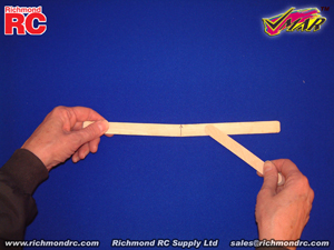
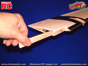
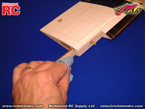
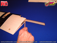
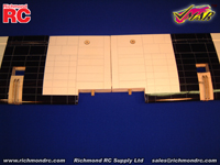
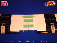
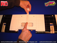
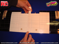
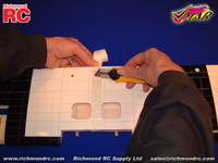
| 1.54.1.3. VMA-T210X Twin Otter 09-15 ARF - Important Information |
|
| COPYRIGHT |
Copyright Richmond RC Supply Ltd. All rights reserved.
|
| 1.54.1.3.1. VMA-T210X Twin Otter 09-15 ARF - Covering |
This model uses POLYCOTE ECS Covering |
| POLYCOTE ECS - Care & Maintenance - Quick Tips |
|
Question: Do you have any pointers regarding the Care & Maintenance of POLYCOTE ECS? Answer: Yes we have this Summary of Quick Tips. See www.richmondrc.com ( Enter Site > Support Services > Knowledge Base then Search on "Covering") for an expanded explanation of each Tip. Polyester offers the best in covering performance and as with any new modern technology, the maintenance methods may be different than those you used with your older covering. This is NOT Monokote or Solarfilm, its different. If you have used ORACOVER or ULTRACOTE you will have some experience with working with POLYESTER as a covering material. Here is our Summary of Quick Tips related to POLYCOTE ECS covering.
|
| 1.54.1.4. Support |
On Line, eMail, Fax, Phone, Mail |
| We offer the Best in Support Services. |
We back up our products and our customers with the best support services available. From our industry leading Knowledge Base to information about your Shipment, we've got you covered!
To access our Support Services please:
Your Choice of Support Services that Work for You:
|
| 1.54.1.4.1. Contact Us |
For Sales and other Inquiries |
| Support - Contact Us - Reach our Sales Department by eMail, Fax, Phone or Mail |
Technical Inquiries: Please review the information provided in our Knowledge Base. After checking our Knowledge Base, if you need further assistance please use our Submit A Question service to get a response within 2 Business Days.
Sales Inquiries: Please note that our Sales Department personnel are trained and dedicated to:
Their depth of technical knowledge is about on par with what is shown in our printed sales literature. In most cases, they are working from the same printed advertisements or content from our web site that you are. Asking sales personnel to confirm the size, color and availability of a product is well within their capabilities. However, asking detailed questions about technical issues is not.
Buy our Products:
For All Other Inquiries... please consult the following resources:
|
| 1.54.1.5. Keep Up to Date |
Check Frequently for Updates |
| Support - Stay Current - Check Frequently for Updated &/or Additional Information |
This information is subject to change without notice. When viewing this information in a printed form the printing date will be visible in the lower right corner. Check frequently for updates &/or Additional Information.at www.richmondrc.com, > Enter the Site, > Support Services, follow the links to our Knowledge Base. Review the Table of Contents and search for the name and/or part number of this product.
For automated notification of changes to information contained in our Knowledge Base please register as a Priority Response member and subscribe to our Priority Response Notification Service.
|
| 1.54.2. VMA-T210X Twin Otter 09-15 ARF - Additional Information |
In general "Additional" Information is:
Subject to the Conditions of Use, please review the attachments and related articles listed below. |
| COPYRIGHT |
Copyright Richmond RC Supply Ltd. All rights reserved.
|
| 1.54.2.1. VMA-T210X Twin Otter 09-15 ARF - Aileron Control Rod Length |
Question: The aileron control rods that run from the servo to the aileron control horn on my VMAR Twin Otter appear to be slightly too long. What should I do?
Answer: The Twin Otter wing has been produced in several different configurations depending on the market area. Early production runs shipped to Europe and the UK used a one piece wing. Later production runs and all shipments to North America used a two piece wing. The aileron control rod length is adjustable to fit the wing that you have.
For each aileron: 1) Ensure that your servo is mounted correctly and that the servo arm can rotate freely the way you have installed it. Center the servo arm so that it lies parallel to the wing trailing edge. 3) Install the control horns on the ailerons. Tape the ailerons into a neutral position as explained in the manual. 4) If you find that the aileron control rods are too long, use a ruler to measure how much shorter you need to make the rod.
5) If in any doubt about the security of the coupling, unthread the clevis and wick thin CA into the coupling between the stud and the plastic tube. Do not get CA into the clevis threads. |
| 1.54.2.2. VMA-T210X Twin Otter 09-15 ARF - Extra Hardware Items |
Question: I have completed the assembly of my VMAR Twin Otter and I have a few extra hardware items such as horns, screws and wing bolts. What are these for?
Answer: We usually include a few extra horns and wing bolts with all VMAR ARF's. You may also find a spare clevis and a couple of small screws depending on the model. These are free and intended to help you out if you drop or misplace one of these small items. If you have followed all of the assembly steps, completed your model, tested that your radio and control surfaces all move correctly, tug tested everything twice, just put any of extra hardware pieces in one of the bags and set it aside as spares just in case you need them later on. Don't throw anything out, you just never know when that screw, horn or nut may be needed!
|
| 1.54.2.3. VMA-T210X Twin Otter 09-15 ARF - Pilots - What sizes fit? |
Question: Can pilots be installed in the VMAR Twin Otter? If so what are the dimensions that I should keep in mind when selecting pilots?
Answer: Yes pilots (2) can be installed in the VMAR Twin Otter. The factory seats and shoulder harnesses are installed and the seats have a flexible back that facilitates installation of after market pilots working from inside the main radio bay of the fuselage. Here are some approximate dimensions for reference purposes when selecting pilots.
|
| 1.54.2.4. VMA-T210X Twin Otter 09-15 ARF - Glow Power - Tips |
Question: Can I use glow engines to power my VMAR Twin Offer? If so what sizes are recommended? Any tips you can suggest on what I need to plan for?
Answer: Yes the VMAR Twin Otter can be powered with glow engines. We suggest glow engines be at least .09 cu. in. each as a minimum. Maximum engine size should be limited to .15 cu. in. each. Please note that setting up and operating multiple glow engines is not for novices. It requires considerable expertise with modeling, glow engines and RC flying to be able to successfully equip and fly the Twin Otter with glow engines.
Tips on use of glow power: 1) We recommend two stroke engines for this model. Four stroke engines tend to be bigger and heavier and they may cause structural failure of the standard wood engine mounting pylons.
2) You will need to plan your fuel tanks and engine mounting system with careful consideration for physical space particularly if you wish to try to install the engines so that you can utilize the scale like engine shrouds and nacelles.
3) Do NOT glue the engine mounting pylons (factory assembled of wood) to the wing until you have test fitted the engine mounting pylons, engine mounts, engines, mufflers, fuel tanks, fuel tubing, throttle linkages, engine shrouds and nacelles.
4) Once you have test fitted all of the components related to the glow engines, use 30 Minute Epoxy to attach the engine pylons to the wing. Ensure they are aligned and fitted properly. Let the adhesive cure thoroughly before proceeding.
5) Use Pacer Finishing Resin and a brush to throughly seal any exposed wood, particularly that of the engine mounting pylons and the attachment area on the wing. Also the wing saddle area. The exhaust from glow engines contains lots of hot vapourized and liquid oil residue. Although most of this oil will be channeled out in the exhaust, some oil will inevitably get on the model itself and will be absorbed by any unsealed wood. Oil can weaken glue joints and the wood itself.
6) Glow engines tend to produce considerable vibration particularly in a twin configuration when the engines are not quite at the same RPM. Take particular care to balance your props and to run the engines at the same RPM when compared to each other throughout the range of throttle positions. Vibration can cause fuel feed problems, lean runs and engine cut off as well as structural failure, control surface flutter and/or separation and is very damaging to servos. It is very important to keep vibration to a minimum.
|
| 1.54.2.5. VMA-T210X Twin Otter 09-15 ARF - Steering Control Rod for Nose Gear |
Question: Where is the steering control rod for the nose gear packed for shipping? What does it look like? I can't seem to locate it. Also, please provide any tips you may have for installing it.
Answer: The Twin Otter steering control rod for the nose gear is shipped in the fuselage main radio and forward bay. It is usually located near the left side. The rod is about 15.75 in. (654 mm) long. The inner rod is solid metal and the outer (shorter) rod is a semi transparent plastic tube. There is an EZ connector near the servo end of the metal rod and a Z-bend at the steering arm end of the metal rod.
Installation is described in the manual that came with the model and can be summarized as follows: 1) The Z-bend engages with the steering arm. The EZ connector attach's to the servo arm and the metal control rod.
2) Loosen the EZ connector set screw and remove the EZ connector from the metal rod.
3) Remove the steering arm from your servo.
4) Attach the EZ connector to the servo arm using the nut to fasten it.
5) Slide the EZ connector onto the metal steering control rod leaving the servo arm attached.
6) Attach the servo arm to the servo. Align the nose gear and steering servo in a neutral position for straight ahead motion. Secure the servo arm to the servo.
7) Tighten the EZ connector set screw to engage the steering control rod.
8) Leave about .5 in (12 mm) of extra rod protruding beyond (aft) of the EZ connector. Snip off any excess length.
|
| 1.54.2.6. VMA-T210X Twin Otter 09-15 ARF - Steering Direction sync with Rudder Direction |
Question: I am using a Y-harness in my VMAR Twin Otter to enable control of the rudder and the nose gear steering using the rudder channel on my receiver. Will this automatically result in the steering direction on the ground using the nose gear being in sync (the same direction) as the rudder steering in the air?
Answer: It depends on your servo type and installation but in any event it's easy to sync the nose gear and rudder steering so that they are both moving in the correct direction even though you are controlling the two servos via a Y-harness from the rudder channel of your receiver.
1) First of all try it out. If the nose gear is moving in sync with the rudder you are good to go. 2) If they are not in sync please see your Assembly and Operations Manual. Look at pictures 12C and 12F and the picture in the Stage 12 introduction. Picture 12F shows the rudder control rod attached to the servo steering arm that is pointing up. To reverse the direction of the movement of the rudder move the rudder control rod to the opposite side of the rudder servo. 3) OR you can do the following: See pictures 20B, 20C, 21.1 and 21.2. These show the steering control arm connected via an EZ Connector attached to the left side of the steering servo arm. To reverse the direction of movement of the steering nose gear move the steering control rod and EZ Connector to the opposite side of the steering servo. |
| 1.54.3. VMA-T210X Twin Otter 09-15 ARF - Assembly & Operations Manual in PDF format |
| 1.54.4. VMA-T210X Twin Otter 09-15 ARF - Pictures, Graphics & Artwork |
| 1.54.4.1. Logo VMA-T210X Twin Otter 09-15 ARF |
| 1.54.4.1.1. Logo (CMYK_TIF) VMA-T210X Twin Otter 09-15 ARF |
| 1.54.4.2. Pictures VMA-T210W Twin Otter 09-15 ARF - White |
| 1.54.4.2.1. Pictures (CMYK_TIF) VMA-T210W Twin Otter 09-15 ARF - White |
| 1.55. VMA-U160X V-Stik 60 ARF Hi Wing Sport 68" |
| 1.55.1. VMA-U160X V-Stik 60 ARF - CG Location - Where is it? |
Question: The manual for the V-Stik 60 is the same as for the V-Stik 40. Is the CG the same for both models? What is the CG location for the Stik 60? Answer: For the Stik 60, use 3-1/4" for the first flights and then if you wish to increase the aerobatic performance of the Stik 60, move the CG back until the CG is located at .25-.5" ahead of the thickest part of the wing. You can move slightly further aft for extreme maneuvers but test each 1/4" step and under no circumstances do we recommend locating the CG more than 4" back from the leading edge of the wing. |
| 1.55.2. VMA-U160X V-Stik 60 ARF - Electric Power Conversion |
For those of you who may be wondering about flying a VMAR V-Stik 60 ARF using Electric Power here is an equipment report from a modeler who has electrified his V-Stik 60 ARF as follows:
Please note that this report comes from a modeler flying near Durango, CO at approximately 7000 feet above sea level. A lower pitch and/or smaller diameter prop could be used at lower elevations. See the article included below for more information re adjusting for altitude when flying electric.
|
| Electric Power - Performance at High Altitudes |
Question: I live at 5000 feet above sea level. What should I do to get my electric power system to perform at high altitudes as well as it does at sea level? Answer: It's tough to get the same performance at 5000 or 8000 feet as you do at sea level but we do have a technique that will help you come close. First of all it's important to understand a few things: 1) Unlike an internal combustion engine (i.e. glow or gas), an electric motor does not consume oxygen and hence could care less about oxygen or anything else that affects combustion. 2) An electric motor system that runs well at sea level will underperform at higher altitudes not because the air has less oxygen but because the air is thinner. Hot weather does the same thing... the air gets thinner. Hot and high together can really gang up and take a chunk out of the performance. In order to get your electric motor system to perform in thinner air the same way it does at sea level, you may actually have to change the motor, speed control, battery pack and prop but before you go reaching for your credit card here is a technique that attacks the problem from the lowest cost component first.
Be cautious when testing to ensure that the motor, ESC and battery do not overheat with the new prop. Some compromising may be necessary to get good performance that does not overheat components. In a perfect world, you would carefully select a specific motor, ESC, battery and prop to get the ideal combination for high altitude performance when installed in a particular model. Yup... perfect is best... but for those of us who can settle for a bit less than ideal and have limited budgets, changing the prop to generate similar thrust in high, hot & thinner air as you get in low, cool & thicker air is a good low cost way to go.
|
| 1.55.3. VMA-U160X V-Stik 60 ARF - Landing Gear - Trike or Tail Dragger? |
Question: Does VMAR V-Stik 60 ARF have trike gear or is it a tail dragger? Answer: The VMAR V-Stik 60 ARF is a tail dragger. |
| 1.56. VMA-X140X Xtreme Stik 40-52 ARF ECS Shoulder Wing |
| 1.56.1. VMA-X140X - Wing Control Surfaces - Quad Flaps - What does it mean? |
|
| VMA-X240X - Wing Control Surfaces - Quad Flaps - What does it mean? |
Question: What do you mean by Quad Flaps? Answer: The VMAR Xtreme Stiks come with quad flaps in the wing. There are four control surfaces and each can be controlled by its own servo. There are two ailerons and two flaps. Better Answer: Using a computer radio this four surface, four servo arrangment helps with XTREME aerobatics that the Xtreme Stik was designed for. Normally, you would set up ailerons using two servos and the outboard control surfaces and you would set up flaps using two servos and the inboard control surfaces. With an appropriate computer radio, you can also configure the flaps as flaperons so that when flaps are deployed the ailerons act as flaps also. Spoilers and spoilerons (raised "flaps") are also possible using a computer radio.
|
| 1.57. VMA-X240X Xtreme Stik 40-52 ARF ECS Low Wing |
| 1.57.1. VMA-X240X - Wing Control Surfaces - Quad Flaps - What does it mean? |
Question: What do you mean by Quad Flaps? Answer: The VMAR Xtreme Stiks come with quad flaps in the wing. There are four control surfaces and each can be controlled by its own servo. There are two ailerons and two flaps. Better Answer: Using a computer radio this four surface, four servo arrangment helps with XTREME aerobatics that the Xtreme Stik was designed for. Normally, you would set up ailerons using two servos and the outboard control surfaces and you would set up flaps using two servos and the inboard control surfaces. With an appropriate computer radio, you can also configure the flaps as flaperons so that when flaps are deployed the ailerons act as flaps also. Spoilers and spoilerons (raised "flaps") are also possible using a computer radio.
|