| 1. VMA-T210X Twin Otter 09-15 ARF - READ ME FIRST | PLEASE READ ME FIRST
BEFORE PROCEEDING TO ASSEMBLE OR OPERATE THIS PRODUCT

|
| LIABILITY DISCLAIMER & COPYRIGHT NOTICE | LIABILITY DISCLAIMER
The authors and/or suppliers and/or disseminaters of this information and/or product expressly disclaim any warranties or representations, either expressed or implied, including but not limited to implied warranties of fitness, accuracy, timeliness or applicability of the information and/or product provided here. In no event will the authors and/or suppliers and/or disseminaters of this information and/or product have any obligation arising from contract or tort, for loss of revenue or profit, or for indirect, special, incidental, consequential or other damages of any sort arising from this information and/or product. In using this information and/or product, the user accepts all responsibility for and all liability associated with such use.
PROCEEDING WITH THE USE OF THIS INFORMATION AND/OR PRODUCT INDICATES AGREEMENT WITH AND ACCEPTANCE OF THE LIABILITY DISCLAIMER.
|
| Please Note the following Caution | CAUTION
A Remote Control (RC) model aircraft is not a toy. It is a flying model that functions much like a full size airplane. If you do not assemble and operate model aircraft properly you can cause injury to yourself and others and damage property. DO NOT FLY a model aircraft unless you are qualified.
You are ultimately responsible for the mechanical, aeronautical and electrical integrity of any model you fly and all of the components that make up the model including but not limited to the airframe itself, control surfaces, hinges, linkages, covering, engine, motor, radio, servos, switches, wiring, battery and parts. Check all components before and after each flight. It is essential that you act with the clear understanding that you are solely responsible for all aspects of the model at all times. DO NOT FLY until it is right.
|
| 1.1. VMA-T210X Twin Otter 09-15 ARF - General Information |
|
| COPYRIGHT | Copyright Richmond RC Supply Ltd. All rights reserved.
|
| Tips for Avoiding Common Problems |
We have supplied thousands and thousands and thousands of model aircraft in the past 20 plus years. We're not bragging! We tell you this to give some credibility to our suggested list of tips that follow. In talking to modelers around the world, here is what we have found is the key to...
AVOIDING 90% of PROBLEMS that can arise:
- READ THE CAUTION ABOVE & READ THE LIABILITY DISCLAIMER.You are responsible for all aspects of any model you fly. You're It!
- READ ALL DOCUMENTATION before doing anything else!
- INSPECT CAREFULLY immediately upon arrival!.
- RETAIN ALL PACKAGING until the checkout is complete! If you need to return anything you must have all of the original packaging.
- READ & LOOK! At everything! Do it once & then do it again.
- REMEMBER WHAT "ARF" STANDS FOR. ARF means ALMOST Ready to Fly with an emphasis on ALMOST! Some assembly and modeling skills are required.
- ALLOW ENOUGH TIME to enjoy the assembly process! Rushing into a 6 hour job with 3 hours to spare simply will not work. This is a Hobby... take your time.
- DRY FIT & TEST ASSEMBLE EVERYTHING before you glue anything!
- USE 30 MINUTE EPOXY when joining wings & installing stabilizers and other structural components but only after you have dry fitted and test assembled the components without glue! Once parts are glued together they cannot be unglued and they cannot be returned or replaced without charge.
- PLAN AHEAD! BE CAREFUL! If you get into trouble, DON'T PANIC. Review everything again, talk it over with an experienced modeler and if still in difficulty consult our Support Services.
- TEST TEST!!! TUG TUG TUG!!! EVERYTHING... BEFORE & AFTER EACH FLIGHT! Your model may have been largely pre-constructed and may have pre-installed control rods, hinges, control surfaces and many other essential components. Hinges may have been pinned after they have been installed. However, you must double check every control surface and component before and after each flight. You and only you are responsible for the integrity of all components and the integrity of the model itself. Check everything before and after each flight. Tug on control surfaces, control rods, mounting bolts, T-nuts, mounting plates... tug on everything!
- DO NOT OVER TIGHTEN WING BOLTS or other fasteners. You want bolts and nuts snugly tight and if metal you can use a medium grade thread locker such as Pacer Z42 to help them stay tight. Fasteners must be snug and secure. However a model airplane is not a farm tractor or a garbage compactor. You do not need a pipe wrench or an electric drill to tighten up wing bolts or any other fastener. Leave your plumbing and power tools at home.. hand tools only and go easy on the torque... snug and secure... not stripped or torqued until they squeak or break. Wing bolts can take tremendous torque before breaking... but when you over tighten them or use an electric screw driver on a set of wing bolts, long before the bolts break you can fracture the fuselage, crack the mounting blocks or pull the heads of the bolts through the wing... these problems have a nasty habit of revealing themselves when you least expect the wing to fall off!
- DO NOT OVERPOWER ANY MODEL! Stay within the recommended power range for the model. If you overpower the model you run a high risk of structural failure that will lead to loss of control and a subsequent crash that will destroy the model and may cause injury and/or property damage.
- ASSUME NOTHING! Remember the old yarn about what happens when you ASS-U-ME something. Check everything repeatedly and frequently and DO NOT FLY any model unless you are satisfied that everything is in good working order.
|
| 1.2. VMA-T210X Twin Otter 09-15 ARF - Supplement to the Manual |
|
| 1.2.1. VMA-T210X Twin Otter 09-15 ARF - Electric Power - Options | Question: My VMAR VMA-T210X Twin Otter 09-15 ARF uses two motors. What do you recommend for a power system?
Answer: We have a couple of options for you to consider:
1) Our VMAX Power Module for the Twin Otter is #VMM-T210XPM1. This consists of two of our VMAX Brushless Motors (#VMC-120B15VC) and two of our VMAX Electronic Speed Controls (ESC) (#VMC-120B15VC). Each motor and ESC has been factory mounted to a power pylon ready to mate with the wing.
2) Our VMAX Power Pack for the Twin Otter (#VMM-T210XPP1) contains the Power Module plus a LiPO battery pack, parallel wiring harness, receiver throttle Y harness and propellers. .
Both of these options have been tested with the Twin Otter and help you get into the air quickly and stay there!
|
| 1.2.2. VMA-T210X Twin Otter 09-15 ARF - Electric Power - Wiring | Question: My VMAR VMA-T210X Twin Otter 09-15 ARF uses two motors. How should I wire these up so that I can control them from the single throttle channel on my receiver?
Answer: The simplest solution is to use our VMAX Power Pack which comes with brushless motors, electronic speed controls (ESC), battery pack, propellors etc and includes a custom made Wiring Harness Set for the Twin Otter power and control system. The Power Pack for the Twin Otter is #VMM-T210XPP1.
If you have your own motors, servos, speed controls etc that you intend on using in the VMAR Twin Otter the manufacturer of these electric components is your best bet for advice on operating in a Twin Power configuration. The Wiring Harness Set for the Twin Otter (#VMA-T210XWHS) is available as an aftermarket accessory and in most installations will make it much easier to work with the VMAX Power Module, third party motors, speed controls and servos.
If you have purchased the VMAX Power Pack for the Twin Otter (#VMM-T210XPP1) please follow the installation instructions that come with the Power Pack. The VMAX Power Pack will save you hours and hours of time and greatly reduce the chances of making an expensive mistake.
If you are using third party power components, follow their instructions. In the absence of specific information from the manufacturer here are some general tips that may assist you. Remember, without specific information from the supplier of your Motors and ESC, you run the risk of doing something wrong and such booboos are usually expensive. Use our tips with this in mind. We can't verify that these tips will work with third party equipment and strongly encourage you to obtain information from the manufacturer of your Motors and ESC.
a) Use two idential Brushless Motors and two identical Electronic Speed Controls (ESC). Each motor should have its own speed control. (see footnote below)
b) Connect each ESC to a Brushless Motor using the color coded wire as a guide. Test and ensure that the motor turns in the direction expected and that thrust is aft of the motor.
c) Make a power Y-connector to feed power from your LiPo battery to the power input leads on both of your ESC's.
d) Use the power Y-connector to connect the power input to the ESC's to a common (1) LiPO battery source.
e) Make a throttle Y-connector. This is necessary for DUAL ESC operation which assumes that you are using two motors and two ESC's.
For DUAL ESC operation use ONLY the NEGATIVE (-) Power (usually black or brown) & SIGNAL lines
(see table below) between the receiver throttle channel and the ESC's.
Do NOT use the POSITIVE (+) Power (usually Red) wires.
The following table serves as a guide to common radio systems and their wiring schema and color usage. Use this table with caution. If in doubt, please defer to information provided by your radio supplier.
| RADIO BRAND |
NEGATIVE (-) |
SIGNAL |
| VRS & Futaba |
Black |
White |
| Airtronics Z |
Black |
Blue |
| JR |
Brown |
Orange |
| HiTec |
Black |
Yellow |
f) Plug the ESC throttle control wires into the ends of the throttle Y-connector
g) Plug the remaining single end of the throttle Y connector into your receiver throttle channel.
h) Use the airborne battery pack from your radio system to power your receiver. Do NOT attempt to use power from either BEC to power your receiver. You may wish to consider using a stand alone BEC such as that from Western Robotics to power your radio system but do NOT use the BEC's that are a part of many ESC's. They will not work in a twin power configuration.
i) Select suitable propellers for your motors and your speed controllers. The two props should be identical. Prop selection is vital with brushless motors. Overloading the motors and ESC by using the wrong prop can get very very expensive in a big hurry.
j) Verify that you can control the RPM of the motors via the receiver and that they produce similar RPM and thrust throughout the throttle range.
Footnote: There are some dual ESC's that enable you to control two Brushless motors from one ESC. These eliminates the need for a second ESC and may make the installation of third party components simpler. If you are using a dual ESC, ensure that you follow the manufacturers instructions regarding wiring and operations.
|
| 1.2.3. VMA-T210X Twin Otter 09-15 ARF - Wing - One Piece or Two? | Question: My VMAR VMA-T210X Twin Otter 09-15 ARF refers to a one piece wing. The Twin Otter I received has a two piece wing. What's the story here?
Answer: In some markets, shipping carriers such as UPS charge an additional surcharge for longer boxes. In these markets we have reduced the length of the box by shipping the wing in two pieces in order to save the end consumer from having to pay surcharges on freight.
Additional Information: If your wing was shipped in two pieces, use the wing joiner and 30 minute epoxy to join the wing halves. A roll of wing joint tape has been supplied to seal the joint after the epoxy has cured. USE ONLY 30 MINUTE EPOXY when joining wing halves.
A subsequent article provides detailed instructions for joining the halves of two piece wings.
|
| 1.2.4. VMA-T210X Twin Otter 09-15 ARF - (Stage 0) Wing Assembly - Joining the Wing Halves |
|
In some markets we have reduced the length of the shipping box by shipping the wing in two pieces in order to save end consumers from having to pay surcharges on freight. The Assembly and Operations Manual (version 20061031) does not include instructions for joining the wing halves.
If your wing was shipped in two pieces, BEFORE BEGINNING Stage 1 of the Assembly and Operations Manual please COMPLETE THE FOLLOWING "Stage 0" INSTRUCTIONS in order to assemble your wing.
|
| Parts Supplied:
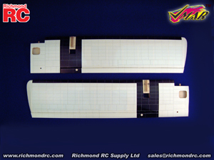
- Right and left wing panels
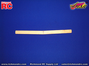
- Wing joiner (also called dihedral brace)
- Roll of wing joint tape
|
Tools & Adhesives needed:
- 30 minute epoxy. Pacer Zepoxy #PAC-30ZPOXY8
recommended. (Do not use 5 Minute Epoxy)
- Epoxy brush or stir sticks
- Disposable mixing dish for the epoxy
- Sandpaper (Coarse 240 grit recommended)
- Low tack masking tape
- Pencil, knife and ruler
- Paper towels
|
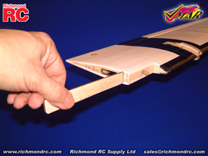
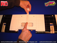
Step 0.1 Locate the wing joiner (also called Dihedral brace). Use a ruler, determine the center of the wing joiner and mark a center line with a pencil as illustrated in 0B.
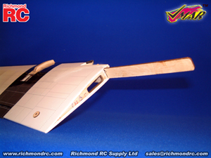
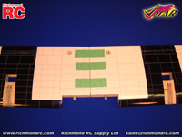
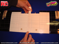
Step 0.2 Locate the wings (See 0A). Trial fit the wing joiner in the channels in the wing panels. You will see two channels in each wing. The channel closest to the leading edge should NOT be used. Insert the wing joiner into the channel that is slightly further aft in the wing. The wing joiner should insert smoothly up to the center line as illustrated in 0C.
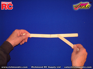
Now slide the other wing panel onto the wing joiner until the panels meet. If the fit is overly tight, sand the wing joiner slightly and try again. Do not apply excessive force. Sand the joiner until a snug fit is obtained. If the panels slide onto the joiner relatively easily but you end up with a slight gap between the wing panels, trim the ends of the joiner by about 1/8 in. (3 mm) and try again. Work in small steps, testing the results between steps.
Mark the joiner to indicate which way is UP as illustrated in 0B.
|
|
|
|
|
0A - Left & right wing panels
|
0B - Preparation of wing joiner
|
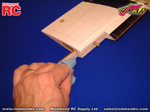
Step 0.3 Apply plenty of 30 minute epoxy to all sides of one end (half) of the wing joiner using a stir stick or epoxy brush as illustrated in 0D. Carefully insert the epoxy coated half of the wing joiner into one wing panel as illustrated in 0E.
See 0F and use a cloth or tissue to wipe away any excess epoxy that squeezes out of the joint.
Repeat this process several times to ensure the wing joiner and cavity are well coated with 30 minute epoxy.
When the wing joiner and cavity are well coated with 30 minute epoxy, insert the joiner to the center line, wipe way any excess epoxy and let dry. (Note: do not use 5 minute epoxy or CA to join the wings).
|
|
|
|
|
0C - Trial fit the wing joiner
|
0D - Apply plenty of 30 minute epoxy to the wing joiner
|
|
|
|
|
0E - Carefully insert the joiner all the way to the center line
|
0F - Wipe off the excess epoxy then allow to cure
|
Step 0.4 When the epoxy holding the wing joiner into the first wing panel has cured, trial fit the second wing panel onto the wing joiner (do not glue without trial fitting first) to ensure that the two wing panels fit without an excessive gap.
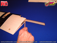
Step 0.5 Now apply plenty of 30 minute epoxy to all sides of the exposed half of the wing joiner (see 0G). Use only 30 minute epoxy to ensure a strong bond and to give yourself plenty of working time. As described in step 0.3, repeatedly apply 30 minute epoxy to the joiner and insert the joiner into the wing joiner cavity to ensure that the wing joiner and the cavity are well coated with 30 minute epoxy.
When you have worked plenty of epoxy into the wing joiner cavity, pull the joiner out of the cavity one last time and apply plenty of 30 minute epoxy to the wing root ribs of both panels. Slide the wings together until the wing roots are firmly in contact with each other and there is no gap remaining between the wing panels (see OH). Epoxy should ooze from the joint and be cleaned off with a rag or tissue before it cures.
Step 0.6 Use low tack masking tape (see 0I) to align the wing surfaces and to hold the wing panels firmly together until the epoxy cures.
|
|
|
|
|
|
0G - Apply plenty of 30 minute epoxy to all surfaces.
|
0H - Align the two wing panels and slowly close the gap until the wing roots are firmly in contact with each other.
|
0I - Use low tack masking tape to hold the wing panels tightly together until the epoxy has completely cured.
|
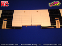
Step 0.7 Once the epoxy has cured completely (allow several hours at least), the masking tape can be carefully removed from the wing panels. Peel the tape back on itself... do not pull upright away from the wing.
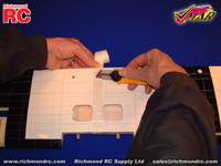
To seal and finish the joint between the wing panels, a roll of wing joint tape has been supplied. Starting on the bottom side of the wing, stick the tape centrally over the joint (see OJ) ensuring that the wing joint tape is pressed down firmly as you work around the wing. Wrap the wing joint tape all the way around the wing in one piece (see OK), starting and finishing on the bottom of the wing (see OL). Trim off any excess tape using a sharp knife.
|
|
|
|
|
|
0J - Apply wing joint tape over the joint starting here on the bottom.
|
0K - Continue applying the tape over the top of the wing, pressing down firmly as you go.
|
0L - Continue back around to the bottom of the wing & overlap the tape where you started. Trim off excess tape.
|
|
|
NEXT STEPS:
If you are installing a VMAX Power Pack or VMAX Power Module or VMAR Wiring Harness Set, please review the instructions that were supplied with these items now.
Otherwise once you have joined the wing halves, please proceed to Stage 1 of the Assembly and Operations Manual to continue with the assembly of your model.
|
|
Pictures are intended to illustrate components and methods of assembly. Production components may vary in detail from that shown.
|
|
| 1.3. VMA-T210X Twin Otter 09-15 ARF - Important Information | |
| COPYRIGHT | Copyright Richmond RC Supply Ltd. All rights reserved.
|
| 1.3.1. VMA-T210X Twin Otter 09-15 ARF - Covering | This model uses POLYCOTE ECS Covering |
| POLYCOTE ECS - Care & Maintenance - Quick Tips | |
Question: Do you have any pointers regarding the Care & Maintenance of POLYCOTE ECS?
Answer: Yes we have this Summary of Quick Tips. See www.richmondrc.com ( Enter Site > Support Services > Knowledge Base then Search on "Covering") for an expanded explanation of each Tip.
Polyester offers the best in covering performance and as with any new modern technology, the maintenance methods may be different than those you used with your older covering. This is NOT Monokote or Solarfilm, its different. If you have used ORACOVER or ULTRACOTE you will have some experience with working with POLYESTER as a covering material.
Here is our Summary of Quick Tips related to POLYCOTE ECS covering.
- Avoid Hot Vehicles
- Cooking your model in your vehicle for hours on end is generally not a good idea! Temperatures can easily exceed 50C (122 F) under such conditions. You will get sags. Consult our Knowledge Base before attempting to remove sags.
- Cleaning After Flying
- We recommend Fantastic household cleaner and disposable paper towels. Mist, do not flood. Wipe along seams, not across. Do NOT NOT NOT NOT use SIMPLE GREEN, 409 or similar materials for cleaning a model airplane.
- Cleaning Initially
- Upon initial inspection if you see a thin streaky film on any of the POLYCOTE ECS, work outdoors and use a paper towel and wipe a slightly wet film of Mineral Spirits over 1/4 of a wing or half a fuselage at a time. Rub gently while still wet. Change towels frequently. Avoid plastics.
- Cutting
- Use sharp scissors or an XACTO knife with a sharp #11 blade.
- Pealing
- Relatively rare. Fix as soon as possible. Consult our Knowledge Base before attempting to resolve.
- Protecting the Finish
- Most Importantly - Follow the cleaning instructions. Use the recommended cleaners and method. Dab away raw fuel. Test small out of the way area and all plastics before applying any glue, solvent, cleaner, paint or other preparation. Patch punctures promptly. Avoid hours and hours sitting in the direct sun.
- Removing & Using Tape
- Use low tack tape. When removing tape , peal the tape back on itself parallel to the surface of the covering.
- Repairing Punctures
- Patch promptly. Clean any oil residue from the area of the puncture. Patch should be 1/2" (13mm) bigger on all sides. Round the corners. Seal in place with a heat iron & sock. Tighten area with a Heat Gun.
- Resealing Seams
- Act promptly. Clean any oil residue from the area and reseal the seam with thin CA.
- Tightening Sags
- Remember SSB... SECURE the perimeter then SHRINK to fit then BOND to the structure. Use an iron with sock to SECURE the perimeter, use a heat gun to SHRINK within the perimeter, use a soft cloth while the covering is warm to BOND the covering to solid substrates.
- Tools for Working with POLYCOTE ECS
- Scissors, XACTO with #11 blade, iron, iron sock, regulated heat gun, soft cotton cloth or glove.
|
| 1.4. Support | On Line, eMail, Fax, Phone, Mail
|
| We offer the Best in Support Services. | We back up our products and our customers with the best support services available. From our industry leading Knowledge Base to information about your Shipment, we've got you covered!
To access our Support Services please:
Your Choice of Support Services that Work for You:
|
| 1.4.1. Contact Us | For Sales and other Inquiries
|
| Support - Contact Us - Reach our Sales Department by eMail, Fax, Phone or Mail | Technical Inquiries: Please review the information provided in our Knowledge Base. After checking our Knowledge Base, if you need further assistance please use our Submit A Question service to get a response within 2 Business Days. Sales Inquiries: Please note that our Sales Department personnel are trained and dedicated to:
- Helping you with non-technical pre-purchase questions,
- Helping you place your order,
- Pointing out any sales, combos or specials that you may wish to consider,
- Inputting your order to our computer system so that it ships out as accurately and quickly as possible... usually the same day,
- Resolving any invoicing problems, and
- Helping to sort out any missing shipment or shipment damage issues.
Their depth of technical knowledge is about on par with what is shown in our printed sales literature. In most cases, they are working from the same printed advertisements or content from our web site that you are. Asking sales personnel to confirm the size, color and availability of a product is well within their capabilities. However, asking detailed questions about technical issues is not.
Buy our Products:
For All Other Inquiries... please consult the following resources:
- On Line Information
- On Line Support Services
- After reviewing our On Line resources, if you require additional assistance please contact us by eMail, fax, phone or mail as follows:
- Ask a Question
- eMail
- Fax
- Phone
- Mail
- Richmond RC Supply Ltd, #114 - 7350 72nd Street, Delta, BC, V4G-1H9
- Mail & printed correspondence only.
- We are not able to accomodate personal site visits or drop-offs/pick-ups at this location.
- Please note that all inbound Shipments require pre-Authorization in advance.
- Unauthorized inbound shipments will be refused.
|
| 1.5. Keep Up to Date | Check Frequently for Updates |
| Support - Stay Current - Check Frequently for Updated &/or Additional Information | This information is subject to change without notice. When viewing this information in a printed form the printing date will be visible in the lower right corner. Check frequently for updates &/or Additional Information.at www.richmondrc.com, > Enter the Site, > Support Services, follow the links to our Knowledge Base. Review the Table of Contents and search for the name and/or part number of this product.
For automated notification of changes to information contained in our Knowledge Base please register as a Priority Response member and subscribe to our Priority Response Notification Service.
|
|