| 1. VMA-E24XX Easy 3D ARF ECS - Various Colors |
| 1.1. VMA-E24XX Easy 3D ARF ECS - Additional Information |
In general "Additional" Information is:
Subject to the Conditions of Use, please review the attachments and related articles listed below. |
| COPYRIGHT |
Copyright Richmond RC Supply Ltd. All rights reserved.
|
| 1.1.1. VMA-E240X Easy 3D 40-52 & Electric ARF - Aileron Horn Hole Location |
Question: We have a VMAR Easy 3D and find that when we install the aileron servos and the aileron control horns they don't quite line up and the control rod ends up not quite perpendicular to the hinge line. Can we move the control horn slightly?
Answer: Yes. Simply redrill the control horn bolt holes so that your aileron control horn aligns better with your aileron servo arm. Depending on your servo arm length and the orientation of your servo you may wish to redrill the new horn bolt hole slightly inboard or slightly outboard of its original location.
To fill in the original hole use Epoxy or a short length of wood dowel.
|
| 1.2. VMA-E24XX Easy 3D ARF ECS - Assembly & Operations Manual |
| 20190602... the manufacturer (VMAR) has supplied a manual for the 45-52 Glow Powered version of this model. The manual for the glow powered model provided with the Glow powered model and with the Electric powered version to serve as a guide to the assembly process. |
| 1.3. VMA-E24XX Easy 3D ARF ECS - Specifications | ||||||||||||||||||||||||||||
|
| COPYRIGHT |
Copyright Richmond RC Supply Ltd. All rights reserved.
|
| 1.4. VMA-E24EX Easy 3D ARF ECS - Using Glow Power |
Question: Is the VMAR Easy 3D intended for electric or glow power? I would like to use glow power. Can this be done?
Answer: Although some Easy 3D's are produced with the assumption that glow power will be used, most are produced with electric power in mind. The airframe is the same in any event. Only the power systems vary.
To use glow power in an Easy 3D that was intended for electric power (i.e. it was not shipped with a fuel tank or glow power engine mount) please see the sub-article below to configure your Easy 3D for glow power using our Glow Engine Installation Pack (#VMA-E240EIP) for the Easy 3D that includes a set of templates and the parts you require. The templates will also be helpful to modelers who are "going it alone" without our Installation Pack.
|
| 1.4.1. VMA-E240EIP Glow Engine Installation Pack for VMAR Easy 3D 45-52 ARF - READ ME FIRST |
PLEASE READ ME FIRST BEFORE PROCEEDING TO ASSEMBLE OR OPERATE THIS PRODUCT
|
| LIABILITY DISCLAIMER & COPYRIGHT NOTICE |
LIABILITY DISCLAIMER The authors and/or suppliers and/or disseminaters of this information and/or product expressly disclaim any warranties or representations, either expressed or implied, including but not limited to implied warranties of fitness, accuracy, timeliness or applicability of the information and/or product provided here. In no event will the authors and/or suppliers and/or disseminaters of this information and/or product have any obligation arising from contract or tort, for loss of revenue or profit, or for indirect, special, incidental, consequential or other damages of any sort arising from this information and/or product. In using this information and/or product, the user accepts all responsibility for and all liability associated with such use. PROCEEDING WITH THE USE OF THIS INFORMATION AND/OR PRODUCT INDICATES AGREEMENT WITH AND ACCEPTANCE OF THE LIABILITY DISCLAIMER.
|
| Please Note the following Caution |
CAUTION A Remote Control (RC) model aircraft is not a toy. It is a flying model that functions much like a full size airplane. If you do not assemble and operate model aircraft properly you can cause injury to yourself and others and damage property. DO NOT FLY a model aircraft unless you are qualified. You are ultimately responsible for the mechanical, aeronautical and electrical integrity of any model you fly and all of the components that make up the model including but not limited to the airframe itself, control surfaces, hinges, linkages, covering, engine, motor, radio, servos, switches, wiring, battery and parts. Check all components before and after each flight. It is essential that you act with the clear understanding that you are solely responsible for all aspects of the model at all times. DO NOT FLY until it is right.
|
| 1.4.1.1. VMA-E240EIP Glow Engine Installation Pack for VMAR Easy 3D 45-52 ARF - General Information |
|
| COPYRIGHT |
Copyright Richmond RC Supply Ltd. All rights reserved.
|
| Tips for Avoiding Common Problems |
We have supplied thousands and thousands and thousands of model aircraft in the past 20 plus years. We're not bragging! We tell you this to give some credibility to our suggested list of tips that follow. In talking to modelers around the world, here is what we have found is the key to... AVOIDING 90% of PROBLEMS that can arise:
|
| 1.4.1.2. VMA-E240EIP Glow Engine Installation Pack for VMAR Easy 3D 45-52 ARF - Important Information |
When mounting your throttle servo you will need to install two mounting rails or a servo tray for the throttle servo. The Glow Engine Installation Pack does not include the rails or servo tray for the throttle servo. |
| COPYRIGHT |
Copyright Richmond RC Supply Ltd. All rights reserved.
|
| 1.4.1.3. VMA-E240X Easy 3D 45-52 ARF - Preparing for Glow Power - Templates |
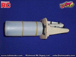
To prepare your Easy 3D for glow power, please review the Easy 3D Assembly and Operations Manual. Note in particular Step 14 Fitting the Fuel Tank and Step 15 Installing the Engine. Pictures 14D and 15A illustrate the engine mount, and power module firewall mounted at a 207 degree angle that works well for the VMAX 46PRO and VMAX 52PRO engines and other engines that have an beam mount spacing of approximately 1.53 in. (65 mm). (This is equivalent to a distance of 2.56 in. (65mm) between the outside faces of the beam mounts when clamped to the motor.)
In addition to an engine such as the VMAX 46PRO or 52PRO or similar two stroke engine you will require a fuel tank, two 7/32" diameter wooden dowels about 3.5 inches long, an engine mount (set of T-beams) and a piece of 3/16" plywood for the firewall. If you purchased the glow engine version of the Easy 3D you will find these parts included with your Easy 3D. If they were not included with your Easy 3D you will need to obtain these items either separately or as a set in our Glow Engine Installation Pack for the Easy 3D.
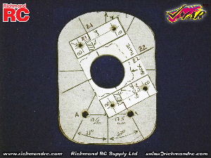
For reference, the individual parts are as follows (included in the Glow Engine Installation Pack #VMA-E240XEIP):
You also will require Pacer ZAP-A-GAP CA+, a Glue Stick such as Super Glue Corp #SGC-GS88 and Pacer Dap-A-Goo or Silicone Sealer such as Super Glue Corp #SGC-THC. You may also require Pacer Finishing Resin and Pacer 30 Minute Epoxy. We have prepared a set of templates to assist you with shaping the plywood firewall, installing the engine mount and modifying the fixed firewall at the front of the fuselage. These Templates are printed on sheets for cutout with scissors and are included with the Glow Engine Installation Pack for the Easy 3D. The Templates also can be downloaded from the attached file links below.
Please note that the Super Glue Corp Glue Stick #SGC-GS88 we have recommended contains a water soluble adhesive that is used to hold the templates into place. Once the work has been completed the templates can be peeled off and the adhesive removed from the wood surfaces using a moist cloth leaving a clean residue free surface.
For tools to make the job easier we suggest a fine toothed scroll saw, Dremel tool with drum sander, sandpaper, a drill or drill press and a set of drill bits.
|
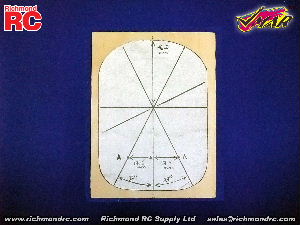
| 1.4.1.4. VMA-E240X Easy 3D 45-52 ARF - Make the Power Module Firewall | ||||
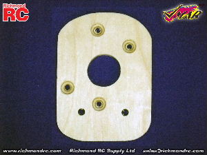
Please review Pictures 14D and 15A in the Easy 3D Assembly and Operations Manual. The power module firewall is the plywood piece that the engine "T-beam" mounts are attached to. The fuel tank is attached to the power module firewall and the fuel tank stopper and in/out tubes extend from the tank forward and through the power module firewall.
Use Template A. Use scissors to trim to the outer perimeter of the power module firewall as shown on Template A. Attach the template to a suitably sized piece of good quality 3/16 inch plywood using a glue stick. You may wish to only attach the center and perimeter of the template to the firewall if you wish to more easily remove the template from your firewall later on.
Center punch the two holes marked A and the center hole at the intersection pont of all of the lines. Drill all three center punch locations with a 7/32" drill.
Use a scroll saw to cut the plywood to match the perimeter shape of the template.
|
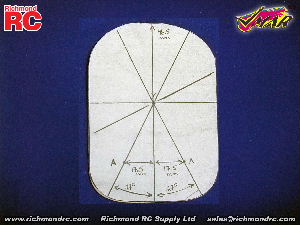
| 1.4.1.5. VMA-E240X Easy 3D 45-52 ARF - Align the Engine Mount (T-beams) | ||||||
After completing the cutting and drilling of your power module firewall, review Pictures 14D and 15A in the Easy 3D Assembly and Operations Manual.
Use Template B. This template is used to position the T-beam engine mounts and subsequently drill the T-beam mounting holes in the power module firewall. This template is for the VMAX 46PRO, 52PRO and similar engines that mount on T-beams with approximately 1.53 in spacing (38mm) between the lug portion of the beams. If your engine mounting lugs require T-beam spacing that cannot work with 38mm spacing you can modify the template by cutting the template vertically along the center line and increasing or decreasing the distance between the resultant template halves to reflect the size of your engine.
The Template B sheet contains a expanded depiction of a typical T-beam mount and engine installation. Use scissors to cut out just the retangle bounded by the T-beam mounts as shown in Template B. Consult the pictures before cutting. You want to end up with Template B looking like the lighter (whiter) shaded paper shown in the pictures below.
Position the center point of Template B over the center line intersection point of Template A on the power module firewall. Rotate Template B 207 degrees counter clockwise from horizontal until the engine lug lines on Template B align with the corresponding diagonal lines (Z1 to Z1 and Z2 to Z2) shown on Template A attached earlier to the firewall. Ensure the center point of Template B remains centered over the fuel tank outlet hole while the lug line remains aligned diagonally. Secure Template B in this position using adhesive from a glue stick.
Use a scroll saw to cut the fuel tank outlet clearance hole in the plywood as shown on the template.
Center punch the four holes marked B. Drill all three center punch locations with a 5/32 inch drill. You can use a 3/16" drill if you wish to provide a bit looser tolerance. After drilling the holes, turn the firewall over and counter sink these four holes from the back of the wirewall using a 27/64 in. drill. Counter sink the holes to a depth of the thickness of a washer (approx 1-1.5mm) at the perimeter of the counter sunk holes.
If you wish to seal the power module firewall, now is the time to do it. This is not mandatory but makes for a neater more professional looking finish. Remove the templates and wipe away any adhesive residue. Blow off any dust. Coat all surfaces with Pacer Finishing Resin. Set aside to cure.
|
| 1.4.1.6. VMA-E240X Easy 3D 45-52 ARF - Install the Engine Mount (T-beams) | ||||
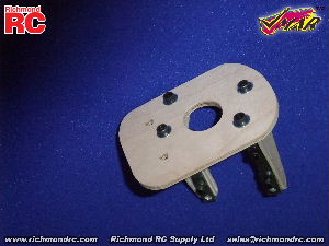
After aligning the engine mount T-beam mounting holes, you are ready to install the engine mounts.
Use four hex head 4mm bolts with washers under the heads. Insert the bolts through the firewall from the backside of the firewall. Position the T-beam mounts as shown in Pictures 14D and 15A in the Assembly and Operations Manual.
Loosely screw all four bolts through the firewall and though the T-beams and into 4 mm nuts before tightening any one bolt or nut. Once all bolts are inserted through firewall and the T-beams and engaged with the 4mm nuts, tighten the bolts and nuts snugly. Ensure the washers on the back side of the firewall sink down into the counter sink holes so that the outer surface of the washers are flush with the back surface of the power module firewall. Wait for 1 hour and then apply Pacer Z42 Blue Threadlocker to the nuts and the threads near the nuts. Retighten the bolts snugly.
|
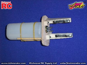
| 1.4.1.7. VMA-E240X Easy 3D 45-52 ARF - Install the Fuel Tank | ||||
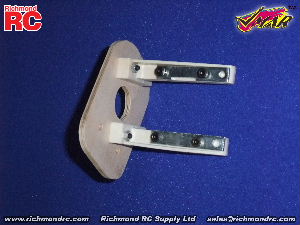
After installing the engine mount T-beams and securing the nuts and bolts please review Step 14 in the Assembly and Operations Manual. Prepare your fuel tank per Step 14 and the associated pictures.
From the back of the firewall, insert the two 7/32 x 3.5 inch dowels into the 7/32 dowel holes drilled using Template A. If you are using 1/4 in. dowels, redrill the holes to 1/4" inside diameter. Insert the dowels only to the point where their forward ends are flush with the forward face of the firewall. You may wish to tap the dowels into the holes using a small hammer. Carefully study the tank tubes and alignment before proceeding. Make sure you know which tube is for what and which way around the tank is. Using Pacer Dap-A-Goo, glue the tank to the dowels and seal both sides of the tank black rubber gasket and tank neck and metal safety ring into place in the firewall center hole. Protect the tubes with tape while sealing. Hold the tank in place with masking tape until the sealant cures. Wick Pacer ZAP-A-GAP CA+ into the dowel holes from the front side of the firewall.
Set aside and let all adhesives and sealants cure.
|
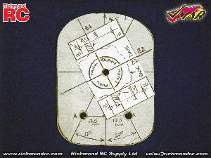
| 1.4.1.8. VMA-E240X Easy 3D 45-52 ARF - Modify the Fixed Firewall in the Fuselage. | ||||
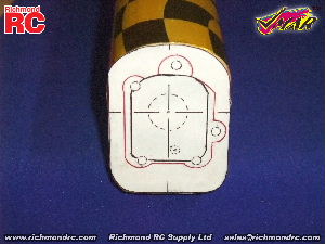
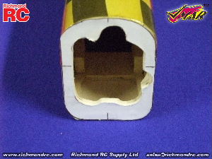
Use Template C. Use scissors to trim to the outer perimeter of the fuselage as shown on Template C. Cut out the inner area of Template C that is bound by the black line. The black line denotes the fixed firewall installed by the factory for electric power systems. Carefully, center, align and attach template C to the forward face of the fixed firewall of the fuselage using adhesive from a glue stick.
Use a Dremel tool and sanding drum to carve away the fixed firewall to match the red line perimeter of Template C. Work in small steps and test the fit of your power module assembly frequently. Continue carving in small steps with frequent test fits until the fuel tank can be easily inserted into the fuselage from the front and the back face of the power module firewall can be pressed flush against the forward face of the fixed firewall while the power module firewall is centered and aligned.
|
| 1.4.1.9. VMA-E240X Easy 3D 45-52 ARF - Temporarily Attach the Power Module to the Fuselage. |
Use two button head sheet metal screws to temporarily hold the power module centered and flush fitted to the front of the fuselage. This will enable you to attach the engine and check the cowl and muffler fit before completing the permanent installation of the power module firewall. We strongly suggest drilling pilot holes for the screws to prevent splitting wood in the fuselage.
|
| 1.4.1.10. VMA-E240X Easy 3D 45-52 ARF - Install Engine, Cowl, Muffler, Spinner & Throttle Control | ||
See Step 15 of the Assembly and Operations Manual to install your engine, cowl, muffler and spinner. Use a Dremel drum sander and sharp scissors to cut out the cowl to fit your engine. Use Template D as a guide for cutting the cowl. Install your muffler and check the muffler clearances through the cowl and around the fuselage. Use an exhaust stack extender if necessary to enable the muffler to clear the fuselage.
See Step 19 of the Assembly & Operations Manual for routing and connection of the Throttle Control.
|

| 1.4.1.11. VMA-E240X Easy 3D 45-52 ARF - Finalize Attachment of the Power Module to the Fuselage. |
After test fitting your engine, cowl, muffler and spinner you are ready to finalize the attachment of the power module to the fuselage.
There are two general ways to go about this, removeable or non-removeable.
If you want to be able to remove the power module for maintenance etc in the future we suggest using four button head sheet metal screws (four #8 x 5/8 Robertson screws provided). Use screws that are just long enough to go through the firewalls but not protrude into the fuel tank area. Choose the screw down points carefully to pick good solid widely distributed areas. Drill pilot holes through both firewalls being careful not to nick or hole the fuel tank.
Wick Pacer ZAP CA into the holes in the fuselage to toughen them up.
Firmly attach the power module to the fuselage using the screws.
If you want to permanently attach the power module to the fuselage, use Pacer 30 Minute ZEPOXY. Apply plenty of ZEPOXY to both the power module firewall and the fixed firewall. Flush the firewalls together ensuring that everything is aligned properly. Hold in place with masking tape or screws for several hours.
Clean away excess expoxy before it cures.
|
| 1.4.1.12. Support |
On Line, eMail, Fax, Phone, Mail |
| We offer the Best in Support Services. |
We back up our products and our customers with the best support services available. From our industry leading Knowledge Base to information about your Shipment, we've got you covered!
To access our Support Services please:
Your Choice of Support Services that Work for You:
|
| 1.4.1.12.1. Contact Us |
For Sales and other Inquiries |
| Support - Contact Us - Reach our Sales Department by eMail, Fax, Phone or Mail |
Technical Inquiries: Please review the information provided in our Knowledge Base. After checking our Knowledge Base, if you need further assistance please use our Submit A Question service to get a response within 2 Business Days.
Sales Inquiries: Please note that our Sales Department personnel are trained and dedicated to:
Their depth of technical knowledge is about on par with what is shown in our printed sales literature. In most cases, they are working from the same printed advertisements or content from our web site that you are. Asking sales personnel to confirm the size, color and availability of a product is well within their capabilities. However, asking detailed questions about technical issues is not.
Buy our Products:
For All Other Inquiries... please consult the following resources:
|
| 1.4.1.13. Keep Up to Date |
Check Frequently for Updates |
| Support - Stay Current - Check Frequently for Updated &/or Additional Information |
This information is subject to change without notice. When viewing this information in a printed form the printing date will be visible in the lower right corner. Check frequently for updates &/or Additional Information.at www.richmondrc.com, > Enter the Site, > Support Services, follow the links to our Knowledge Base. Review the Table of Contents and search for the name and/or part number of this product.
For automated notification of changes to information contained in our Knowledge Base please register as a Priority Response member and subscribe to our Priority Response Notification Service.
|