1. Power Module Set - For VMA-P210X PC9 & Texan II - Brushless Motor, ESC & Firewall


VMM-P210XPM1 POWER MODULE SET


1.1. Power Module Set - #VMM-P210XPM1 For VMA-P210X PC9 & Texan II - READ ME FIRST
PLEASE READ ME FIRST


BEFORE PROCEEDING
TO ASSEMBLE OR OPERATE THIS PRODUCT


LIABILITY DISCLAIMER & COPYRIGHT NOTICE

LIABILITY DISCLAIMER

The authors and/or suppliers and/or disseminaters of this information and/or product expressly disclaim any warranties or representations, either expressed or implied, including but not limited to implied warranties of fitness, accuracy, timeliness or applicability of the information and/or product provided here. In no event will the authors and/or suppliers and/or disseminaters of this information and/or product have any obligation arising from contract or tort, for loss of revenue or profit, or for indirect, special, incidental, consequential or other damages of any sort arising from this information and/or product. In using this information and/or product, the user accepts all responsibility for and all liability associated with such use.

PROCEEDING WITH THE USE OF THIS INFORMATION AND/OR PRODUCT INDICATES AGREEMENT WITH AND ACCEPTANCE OF THE LIABILITY DISCLAIMER.
 
Please Note the following Caution

CAUTION

A Remote Control (RC) model aircraft is not a toy. It is a flying model that functions much like a full size airplane. If you do not assemble and operate model aircraft properly you can cause injury to yourself and others and damage property. DO NOT FLY a model aircraft unless you are qualified.

You are ultimately responsible for the mechanical, aeronautical and electrical integrity of any model you fly and all of the components that make up the model including but not limited to the airframe itself, control surfaces, hinges, linkages, covering, engine, motor, radio, servos, switches, wiring, battery and parts. Check all components before and after each flight. It is essential that you act with the clear understanding that you are solely responsible for all aspects of the model at all times. DO NOT FLY until it is right.  


1.1.1. Think Safety
When working with Batteries, Electric Models, Motors & Propellers, Chargers & Electrical Devices
 

ALWAYS DISCONNECT THE BATTERY 

or other electrical power source from any motor, device or charger when transporting, storing, not using or when you are not in attendance.
 
Keep hands, tools, clothing and all foreign objects well clear of equipment prior to and during operations. Take particular care to safeguard and protect your eyes and fingers and the eyes and fingers of other persons who may be nearby.
 
STAY CLEAR OF PROPELLER. PROTECT YOURSELF & OTHERS AT ALL TIMES
 
Use only a good quality propeller that has no cracks or flaws. Ensure propellers are securely attached. Stay clear of the propeller and stay clear of the plane of rotation defined by the propeller prior to connecting your battery to any motor or power system.
 
 
1.1.2. Power Module Set - For VMA-P210X PC9 & Texan II - General Information
 
COPYRIGHT
Copyright Richmond RC Supply Ltd. All rights reserved.
 
Tips for Avoiding Common Problems

We have supplied thousands and thousands and thousands of model aircraft in the past 20 plus years. We're not bragging! We tell you this to give some credibility to our suggested list of tips that follow. In talking to modelers around the world, here is what we have found is the key to... 

AVOIDING 90% of PROBLEMS that can arise:  

  1. READ THE CAUTION ABOVE & READ THE LIABILITY DISCLAIMER.You are responsible for all aspects of any model you fly. You're It!
  2. READ ALL DOCUMENTATION before doing anything else! 
  3. INSPECT CAREFULLY immediately upon arrival!.
  4. RETAIN ALL PACKAGING until the checkout is complete! If you need to return anything you must have all of the original packaging.
  5. READ & LOOK! At everything! Do it once & then do it again.
  6. REMEMBER WHAT "ARF" STANDS FOR. ARF means ALMOST Ready to Fly with an emphasis on ALMOST! Some assembly and modeling skills are required.
  7. ALLOW ENOUGH TIME to enjoy the assembly process! Rushing into a 6 hour job with 3 hours to spare simply will not work. This is a Hobby... take your time.
  8. DRY FIT & TEST ASSEMBLE EVERYTHING before you glue anything!
  9. USE 30 MINUTE EPOXY when joining wings & installing stabilizers and other structural components but only after you have dry fitted and test assembled the components without glue! Once parts are glued together they cannot be unglued and they cannot be returned or replaced without charge.
  10. PLAN AHEAD! BE CAREFUL! If you get into trouble, DON'T PANIC. Review everything again, talk it over with an experienced modeler and if still in difficulty consult our Support Services.
  11. TEST TEST!!! TUG TUG TUG!!! EVERYTHING... BEFORE & AFTER EACH FLIGHT! Your model may have been largely pre-constructed and may have pre-installed control rods, hinges, control surfaces and many other essential components. Hinges may have been pinned after they have been installed. However, you must double check every control surface and component before and after each flight. You and only you are responsible for the integrity of all components and the integrity of the model itself. Check everything before and after each flight. Tug on control surfaces, control rods, mounting bolts, T-nuts, mounting plates... tug on everything!
  12. DO NOT OVER TIGHTEN WING BOLTS or other fasteners. You want bolts and nuts snugly tight and if metal you can use a medium grade thread locker such as Pacer Z42 to help them stay tight. Fasteners must be snug and secure. However a model airplane is not a farm tractor or a garbage compactor. You do not need a pipe wrench or an electric drill to tighten up wing bolts or any other fastener. Leave your plumbing and power tools at home.. hand tools only and go easy on the torque... snug and secure... not stripped or torqued until they squeak or break.  Wing bolts can take tremendous torque before breaking... but when you over tighten them or use an electric screw driver on a set of wing bolts, long before the bolts break you can fracture the fuselage, crack the mounting blocks or pull the heads of the bolts through the wing... these problems have a nasty habit of revealing themselves when you least expect the wing to fall off!
  13. DO NOT OVERPOWER ANY MODEL! Stay within the recommended power range for the model. If you overpower the model you run a high risk of structural failure that will lead to loss of control and a subsequent crash that will destroy the model and may cause injury and/or property damage.
  14. ASSUME NOTHING! Remember the old yarn about what happens when you ASS-U-ME something. Check everything repeatedly and frequently and DO NOT FLY any model unless you are satisfied that everything is in good working order.


1.1.3. Power Module Set - For VMA-P210X PC9 & Texan II - Introduction
 
 
Before beginning the Installation Instructions please read the Overview and check off the components provided. Each component is in a labelled parts bag. Please check off the components against the Contents list below. Leave the components in their parts bags for now. Do not remove the components from their parts bags until each is needed during the installation process. 
 
Power Module Set - For VMAR Electric Models - Overview
VMAR Power Module Sets are intended for modelers who already have their own Li Po Battery, Servos, Props and wiring systems but who wish to purchase an easy to install power system including the firewall(s), motor(s) and speed control(s) that have been factory designed for and tested with their VMAR model.
 
1.1.4. Power Module Set - For VMA-P210X PC9 & Texan II - Contents
This VMAX Power Module Set (#VMM-P210XPM1) consists of the following components:
  • (The laser cut wood power module firewall is part# VMA-P210XPMV)
Power Module Set - For VMAR Electric Models - Typical Contents
VMAR Power Module Sets are factory designed for each VMAR Electric Model and contain the firewall(s), electric motor(s) and electronic speed controls(s) (ESC) for the applicable model.

A VMAX Power Module Set typically consists of the following components: 

  • Laser cut wood power module firewall.
    • This may also be supplied with the model (in a parts bag)
  • Brushless Motor (#VMM-111B18VM)
    • With four (4) 3mm socket head bolts and 4 flat washers fitted for shipping.
  • Propellor Mounting Hardware.
    • One (1) 3mm security lock nut is fitted on the threaded motor shaft for shipping.
    • Three (3) 3mm nuts and two (2) #6 flat washers are supplied in a parts bag.
  • Electronic Speed Control ("ESC") (#VMC-120B15VC).
    • Red, White & Black three (3) wire lead set attached to ESC for connection to Brushless Motor.
    • Red (+), Black (-) two (2) wire lead set attached to ESC for DC power input.
      • Two (1 Red, 1 Blue) crimp on female bullet connectors for power battery leads.
    • RC servo plug on Red, White, Black three (3) wire set for connection to RC receiver throttle channel.
    • Four zip straps.
  • READ ME FIRST documentation.

Power Module Sets for Multi-Motor Models:  

  • Power Module Sets for multi-motor models will contain multiple firewalls, motors and speed controls as required to power the model.
  • For each ESC in the Power Module Set we also include 1 Red and 1 Blue female crimp on bullet connector for use with user supplied power leads.
  • For each motor in the Power Module Set we also include propeller mounting hardware.
VMAR Power Module Sets do NOT include:
  • Wiring or connectors other than the leads attached to motor and attached to the electronic speed control and the red and black female bullet connectors noted above.
  • Propeller
  • Li Po Battery Pack 
  • Servos
These components are NOT included in the Power Module Set and will be needed to complete your model. If you do not already have these items, they will need to be obtained separately. 
 
1.1.5. Power Module Set - For VMA-P210X PC9 & Texan II - Installation Instructions
  
 
Consult any labels carefully, particularly the larger WARNING labels. The labels are largely self explanatory. Reading the labels will save you a great deal of time and help prevent damage to your equipment.
 
1.1.5.1. Power Module Set for VMA-P210X PC9 & Texan II - Installation Procedure
a) Review the Read Me First documentation and the Assembly & Operations Manual that came with your model.

b) In the Operations Manual please turn to Page 7, Stage 11.

c) Review (but do not action) all Steps 11A through 11L inclusive.

d) Review Figure 11F showing the wiring between the motor and the electronic speed control ("ESC"). Make sure you plug the wires together as follows:

Motor Red Wire to ESC Red Wire
Motor Black Wire to ESC White Wire
Motor White Wire to ESC Black Wire
If you do not connect the wires between the motor and the ESC as described above you can damage the motor &/or ESC or the motor may turn backwards.

e) Review the supplementary information provided below regarding step 11K

f) After reviewing the steps and the wiring of figure 11F and the supplementary information provided below, proceed carefully with steps 11A through 11L to assemble your power module.

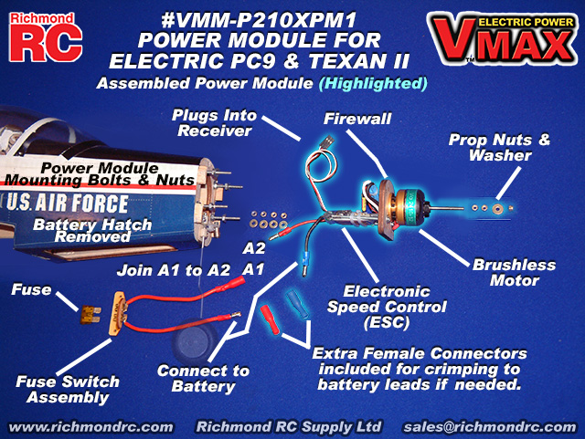
The following depiction illustrates the Fuselage and the assembled Power Module and how it is wired to the Fuse Assembly and Battery Pack:


VMA-P210X PC9 & Texan II 06-12 ARF - Firewall (Power Module) Spacing - Page 7, Figure 11K

This supplementary information applies to manuals with a copyright date of 20070418 (see back cover). Manuals having later copyright dates may already reflect this supplementary information.

Please see Page 7, Figure 11K.

Figure 11K illustrates the spacing between the fixed firewall in the front of the fuselage and the power module firewall to which is attached the motor and speed control.

The picture is correct. However the black type annotated distance shown in Figure 11K of the 20060314 version of the manual is incorrect. The distance should be .5 in. (12.5 mm).

The actual distance is not particularly critital. What is important is that: 

  • The spacing is equal at all four bolt locations.
  • The cowl can be pushed over the motor and power module firewall and back onto the fuselage with an overlap of 1/8 in. (3 mm)
  • The cowl does not touch the motor itself.


1.1.6. Power Module Set - For VMA-P210X PC9 & Texan II - Operating
  
 
Consult any labels carefully, particularly the larger WARNING labels. The labels are largely self explanatory. Paying attention to the operating limits will help prevent damage to your equipment.
 
We developed this Power Module as a "system" suitable for your model. We strongly advise against changing any component within this system. If a component requires replacement, ensure you replace it with a new but identical component to that which is being swapped out.
 
 
1.1.6.1. Propellers - Power Module Operations - VMA-P210X PC9 & Texan II
 
a) See the Warning label on the firewall. Do NOT exceed the maximum propeller size noted.
 
b) With power disconnected, double check the propeller to make sure it is not damaged or nicked in any way and that it is securely and safely mounted. Check before and after each flight.
 
c) Ensure the propeller turns true (no wobble) and that it is balanced and that all propeller fasteners are tight.

USING THE WRONG PROPELLER &/or OPERATING WITH EXCESSIVE VIBRATION WILL DESTROY THE MOTOR.
 
d) Ensure that your propeller is rotating clockwise when viewed from behind (looking forward as if you were in the cockpit) and that the prop is blowing air from the front of the model to the back.
 
f) If the propeller is rotating clockwise when viewed from behind but air is flowing from the back to the front of the model, the propeller is mounted on the motor backwards. Check and reinstall the propeller correctly. In general the brand logo and other writing on propellers should face forwards.
 
g) If the propeller is rotating backwards, reverse the black and white wire connections between the motor and the electronic speed control.
 
1.1.6.2. On the Ground - Power Module Operations - For VMA-P210X PC9 & Texan II
Operating the brushless motor on the ground or in a static mode whereby the aircraft cannot move, puts peak loads on the motor while not providing adequate cooling normally generated in flight. Peak loads coupled with inadequate air flow leads to very rapid heat buildup within the brushless motor that can damage or destroy the motor very quickly.
 
ENSURE ADEQUATE COOLING. DO NOT OPERATE AT HIGH THROTTLE ON THE GROUND FOR LONGER THAN 10 SECONDS.
1.1.6.3. Powering Up - Power Module Operations - VMA-P210X PC9 & Texan II
 
a) Move your throttle stick all the way down to 0 (no power).
 
b) Turn on your transmitter
 
c) Turn on your receiver.
 
d) Ensure the model is held securely in order to test the motor system. Tie it down or hold the fuselage at the back.
 
STAY WELL CLEAR OF THE PROPELLER AND PLUG IN YOUR BATTERY.
 
e) Advance the throttle on your transmitter
 
f) The Electronic Speed Control (ESC) will apply power to the motor and the prop will begin to rotate. Very briefly advance the power to full throttle to ensure the motor spools up to full power. Do this for no more than 2-3 seconds at a time.
 
g) If the ESC beeps rather than makes the motor turn it is because the ESC is being powered up with the throttle stick at a non-zero position. This is a safety feature to prevent rotation of the prop unless you begin from a zero throttle position after each power up.
 
1.1.6.4. Motor Power Auto-Cutoff - Power Module Operations - VMA-P210X PC9 & Texan II
The Electronic Speed Control (ESC) has an embedded "auto-cutoff" controller that will reduce battery power supplied to the motor as the battery reserve begins to run out. This auto-cutoff controller ensures that the battery retains sufficient energy to power the receiver and servos. As the energy reserve in the battery approaches "empty", the auto-cutoff begin to reduce power available for the motor while allocating the remaining energy to provide power for the receiver and servos so that you can maintain flight control using the remaining energy.
 
Land immediately when you detect that the motor power is beginning to fade. Once the power begins to fade, you have a very short time remaining before the ESC will auto-cutoff power to the motor.
 
1.1.7. Power Module Set - For VMA-P210X PC9 & Texan II - No No's & Must Do's
Motors - No No's - That can Destroy Your Motor

Question: Are there any No No's that I should be careful to stay clear of when running my Brushless Motor?

Answer: We have sold many many brushless motors.  From the questions and service requests we get we can pretty well sum up the No No's and Must Do's as follows:

a) Read Everything First! Every instruction! Every Warning Label! Browse our Knowledge Base while you are at it. About 90% of problems can be avoided by Reading First.

b) Do NOT screw up the electrical connections! Polarity is important. If you are not sure, figure it out first... trial and error testing can get expensive!

c) Do NOT exceed the maximum electrical specifications!  Pay attention to the maximum allowable Voltage, Current and Wattage (Volts x Amps).

d) Do NOT use a propeller that is bigger in diameter and/or bigger in pitch than the specifications provided! Use the recommended propeller.
 
e) Do NOT overheat. Ensure adequate cooling by exposing the motor and entire ESC to moving air.

f) Do NOT operate the motor if the prop appears to wobble when you turn it by hand! Look at the back of the hub as you rotate the propeller over by hand. The back of the hub should remain in one plane throughout the rotation, not wobble.

g) Do NOT operate if the motor appears to vibrate! Look at the prop shaft when it first gets going. If it looks blurry to the eyes or sounds strange it is vibrating. Excessive vibration will destroy your motor and possibly hurt your servos as well. Stop and check all bolts for tightness and make sure the prop is turning true (no wobble) and that the prop is balanced.

h) Do NOT operate with loose fasteners! Check bolts, nuts, screws etc for snug tightness. Do not over tighten but keep them snug. Check periodically, particularly after the first few times you use the motor. Use blue thread locker such as Pacer Z42 to help keep fasteners from loosening up. If you find that fasteners are continously loosening up even after the motor has been used many times, you have a vibration issue. Check for sources of vibration. Excessive vibration will destroy your motor.

i) Do NOT operate at High Throttle on the ground or test bench for longer than 10 seconds! High Throttle static operation such as this where the airplane is not moving, induces maximum load on the motor while not providing proper air flow to help cool it. Heat will build up quickly, particularly if the motor is cowled. Heat is bad news. Heat can melt the windings down and quickly destroy the motor.

j) Do NOT operate without a safety fuse system!

k) Do NOT assume an electric motor is the same as a glow or gas engine! An electric motor is very different. Electric motors will attempt to overcome any load they encounter, even to the point of destroying themselves.

l) Do NOT use your plumbing tools or hammer! A brushless motor is not a farm tractor. Small hand tools only. Snugly tight does not mean you tighten things to the point they strip.

m) Do NOT get dirt, water or metal objects into the motor! If you drop a small screw or nut when working on your model, find it first before turning on your motor. Electric motors have strong magnets. Chances are that if you drop something small and metal into your model and can't find it... that it will be inside the motor. Turn the motor over by hand and pay attention to any unusual resistance, grinding or other odd sounds or feel. Find the missing metal item before operating your motor!
 
 
1.1.8. Support

On Line, eMail, Fax, Phone, Mail

We offer the Best in Support Services.
We back up our products and our customers with the best support services available. From our industry leading Knowledge Base to information about your Shipment, we've got you covered!
 
To access our Support Services please:
Your Choice of Support Services that Work for You: 
1.1.8.1. Contact Us

For Sales and other Inquiries  

Support - Contact Us - Reach our Sales Department by eMail, Fax, Phone or Mail

Technical Inquiries:

Please review the information provided in our Knowledge Base. After checking our Knowledge Base, if you need further assistance please use our Submit A Question service to get a response within 2 Business Days.


Sales Inquiries: 

Please note that our Sales Department personnel are trained and dedicated to:

  • Helping you with non-technical pre-purchase questions,
  • Helping you place your order,
  • Pointing out any sales, combos or specials that you may wish to consider,
  • Inputting your order to our computer system so that it ships out as accurately and quickly as possible... usually the same day,  
  • Resolving any invoicing problems, and
  • Helping to sort out any missing shipment or shipment damage issues.
Their depth of technical knowledge is about on par with what is shown in our printed sales literature. In most cases, they are working from the same printed advertisements or content from our web site that you are. Asking sales personnel to confirm the size, color and availability of a product is well within their capabilities. However, asking detailed questions about technical issues is not.


Buy our Products: 
  • From a Retailer
    • Please support your local retailer.    
  • On Line 24x7x365... if your favorite Retailer does not have what you are looking for, please visit one of our On-Line Stores. 
      • For Radio Control,
      • For ZAP Brand CA, cyanoacyrlates, superglue & epoxies
    • www.supplystore.com
      • Supplying ZAP Brand CA, cyanoacyrlates, superglue, epoxies, related accessories and more to End Users & Consumers in the Building Construction, Repair & Maintenance Trades. Also Fine Woodworkers, Stagecraft Artisans, Professional Detailers, Sportsmen & Scale Model Builders.
    • www.zapglue.ca
      • Supplying ZAP Brand CA, cyanoacrylates, superglue, epoxies and related accessories to End Users & Consumers in the Industrial, Manufacturing, Assembly and Laboratory sectors.
  • Order By Fax 24x7x365
    • 604-940-1063
  • Order By Phone M-F 11am-4pm Pacific Time
    • Order Desk 604-940-1066    


For All Other Inquiries... please consult the following resources:

  • After reviewing our On Line resources, if you require additional assistance please contact us by eMail, fax, phone or mail as follows:

    • Ask a Question
    • eMail 
    • Fax
      • 604-940-1063
    • Phone
      • 604-940-1066
    • Mail
      • Richmond RC Supply Ltd, #114 - 7350 72nd Street, Delta, BC, V4G-1H9
        • Mail & printed correspondence only.                
        • We are not able to accomodate personal site visits or drop-offs/pick-ups at this location.
        • Please note that all inbound Shipments require pre-Authorization in advance.
        • Unauthorized inbound shipments will be refused.        

 
1.1.9. Keep Up to Date

Check Frequently for Updates

Support - Stay Current - Check Frequently for Updated &/or Additional Information
This information is subject to change without notice. When viewing this information in a printed form the printing date will be visible in the lower right corner. Check frequently for updates &/or Additional Information.at www.richmondrc.com, > Enter the Site, > Support Services, follow the links to our Knowledge Base. Review the Table of Contents and search for the name and/or part number of this product.
 
For automated notification of changes to information contained in our Knowledge Base please register as a Priority Response member and subscribe to our Priority Response Notification Service.
1.2. Power Module Set - #VMM-P210XPM1 For VMA-P210X PC9 & Texan II - Additional Information

In general "Additional" Information is:

  • In addition to that found in other documentation related to this product,
  • Often reflects feedback &/or questions from users of the product.

Subject to the Conditions of Use, please review the attachments and related articles listed below.

COPYRIGHT
Copyright Richmond RC Supply Ltd. All rights reserved.
 
Power Module Set - For VMAR Electric Models - Propeller Mounting
VMAR Power Module Sets come with propeller mounting hardware that works with the propeller we recommend AND can be adapted to work with most other propellers.
 
a) We include the following: Three (3) 3 mm plain nuts, One (1) 3 mm security nut with fiber insert, Two (2) flat washers.
 
b) For propellers without a collet set and having a round hole in the back of the propeller hub that is bigger than the motor shaft or having a 3mm hexagonal recess in the back of the propeller hub: First thread one of the 3 mm plain nuts onto the shaft and position it about 3/4 in. (19 mm) from the open end of the shaft. Then install one flat washer followed by two of the 3 mm plain nuts (tighten snugly), then the prop, then a second flat washer and finally one of the 3 mm security nuts. Push the propeller towards the motor so that the two plain nuts are inserted into the recess in the back of the propeller hub and the back of the hub is against the adjacent flat washer. Tighten the 3 mm security nut so that the second flat washer is firmly in contact with the front of the propeller hub. In summary, the components are arranged as follows: Motor > 3 mm nut >  flat washer > two (2) 3 mm nuts > propeller >  flat washer > security nut.
  
c) For propellers with a collet set and having a larger recessed round hole in the back or front of the propeller hub that will accomodate a collet: Select a collet that has a center hole 3 mm (approx 1/8 in.) in diameter. Insert the collet into the hole in the propeller hub. From this point on treat the propeller and collet as one unit i.e. the "propeller". Next thread one of the 3 mm plain nuts onto the shaft and position it about 3/4 in. (19 mm) from the open end of the shaft. Then install one flat washer then the prop, then a second flat washer and finally one of the 3 mm security nuts. Push the propeller towards the motor so that the back of the propeller hub is against the adjacent flat washer. Tighten the 3 mm security nut so that the second flat washer is firmly in contact with the front of the propeller hub. In summary, the components are arranged as follows: Motor > 3 mm nut > flat washer > propeller > flat washer > security nut.
 
d) For propellers having a 3 mm (approx 1/8 in.) round hole that runs completely through the propeller hub with no other hole or recess in the back or front of the hub: Thread one of the 3 mm plain nuts onto the shaft and position it about 3/4 in. (19 mm) from the open end of the shaft. Then install one flat washer, then the prop, then a second flat washer and finally one of the 3mm security nuts. Push the propeller towards the motor so that the back of the hub is against the adjacent flat washer. Tighten the 3mm security nut so that the second flat washer is firmly in contact with the front of the propeller hub. In summary, the components are arranged as follows: Motor > 3mm nut > flat washer > propeller > flat washer > security nut.
 
e) For other propellers: We suggest obtaining a "squish" or "cinch" type propeller adapter suitable for 3mm shafts. You may wish to cut the motor shaft to a shorter length. Measure and test carefully before shortening the motor shaft with due consideration for any cowl and/or propeller clearance.